Timers
|
|
Features |
| Principles |
|
| Engineering Data |
|
| Explanation of Terms |
|
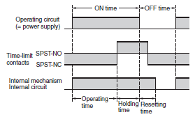
ON Time
The period of time during which the specified voltage is applied to the operating circuit.
OFF Time
The period of time between the moment that resetting begins and the moment that the operating voltage is applied to the operating circuit again. The OFF time is longer than the resetting time.
The period of time from the application of the specified voltage to the operation circuit until the completion of the time-limit contact operation.
The period of time from the completion of the time-limit operation to the start of the reset operation.
Resetting Time
The period of time from the interruption of the voltage supplied to the operating circuit during or after the time-limit operation until the return of the Timer to its initial state.

The resetting time of the Timer is the period of time during which all the internal components including the contacts, pointer, and the circuit components, such as the capacitor, of the Timer are reset.
If the Timer is operated with an insufficient OFF time (i.e., the OFF time is less than the rated resetting time), the normal operation of the Timer cannot be expected. In such cases, the Timer may operate with an insufficient operating time, operate instantaneously, or not operate at all. Be sure that the OFF time of the Timer is the same as or more than the rated resetting time.
Self-reset
To Automatically reset the Timer by interrupting the voltage that is supplied to the operating circuit.
Electrical Reset
To reset the Timer by applying the required voltage to the reset circuit.
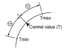
The difference in operating times measured when the Timer repeats operation under the same conditions with a specified set time.
Formula for calculation (with operating time measured more than 5 times):

The difference in the operating times appears as a shift from the central value of operation, so the maximum or minimum values divided by 2 and expressed as plus (+) and minus (-) indication.

If the settings of an Analog Timer is changed while it is performing time-limit operation, the following operation will result.

The difference between the actual operating time and scale time.
Formula for calculation (measurement position can be any scale position as long as it is set to 1/3 min. of the maximum scale time):

For a Time Switch, the setting error is applied for the pulse-output operating time.
Total Error (Time Switch)
A single time rating that combines the setting error, accuracy of operating time, influence of temperature, and influence of voltage.
This rating applies to all measurement results for measurements made under the setting error, influence of temperature, and influence of voltage conditions.
Cyclic Error (Error per Month) (Time Switches)
The error time in the internal clock per month at an ambient temperature of 25°C.
The change in the operating time when the voltage of the control power source changes within the allowable voltage range.
Formula for calculation:
Variation due to voltage change

Influence of Temperature
The change in the operating time when the ambient temperature changes within the ambient operating temperature range.
Formula for calculation:
Variation due to temperature change

OFF Time Characteristics
The change between the operating time for a given OFF time and the operating time when the OFF time is changed.
Formula for calculation:
OFF time characteristic

The OFF time characteristics are determined by the charging and discharging of a capacitor and resistor used in combination as an Electronic Timer. The characteristics vary from ±1.5% to ±5%.
The accuracy of operating time, setting error, influence of voltage, influence of temperature, and OFF time characteristic are used to express the precision of the Timer. Any of these items may be ignored depending on the particular specifications of the model.
The Motor Timer and Electric Timer indicate these items by percentage values. The Count Timer indicates these items by differential time values because the differential range of the Timer's operating time is essentially constant due to operating principles of the Timer. Furthermore, the total error can be indicated to express all these items in the case of the Count Timer.
Vibration Resistance (Malfunction)
The range of vibration during operation in which contacts that are closed will not open by vibration for at least the specified time (1 ms).
Vibration Resistance (Destruction)
The range of vibration in which there is no damage to parts during transport or use, and the operating characteristics are still satisfied.
Shock Resistance (Malfunction)
The range of shock during operation in which contacts that are closed will not open by shock for at least the specified time (1 ms).
Shock Resistance (Destruction)
The range of shock in which there is no damage to parts during transport or use, and the operating characteristics are still satisfied.
Insulation Resistance
The resistance provided by an electrically insulating material between charged metal parts and uncharged metal parts, between control outputs and operating circuits, etc.
Dielectric Strength
The voltage level that will not cause insulation breakdown when applied for 1 minute to the same location as in the insulation resistance measurement.
Impulse Withstand Voltage (AC)
A voltage imposed between the operating power supply terminals or between a charged terminal and non-charged metal part to test the resistance to surge voltages. The impulse withstand voltage imposed between the operating power supply terminals is 3 kV and that imposed between a charged terminal and non-charged metal part is 4.5 kV with both using a ±1.2 × 50-μs standard waveform.
The malfunction and destruction resistance of the Timer against external noise.
The noise immunity of the Timer is checked with a noise simulator, an inductive load, an oscillating relay, and static electric noise.
Mechanical Life Expectancy
The life expectancy of a Timer when the control output of the Timer is operated under a no-load condition.
Electrical Life Expectancy
The life expectancy of a Timer when the control output of the Timer is operated to switch the specified voltage/current load connected to the control output.
The electrical or mechanical life of the Timer is generally indicated by the operating times of the control output. The electrical life is indicated by the operating times of the control output connected to a load and the mechanical life is indicated by the operating times of the control output with no load. The electrical life is shorter than the mechanical life. The lighter the load is, the longer the electrical life will be. Therefore, to prolong the electrical life of the Timer, use the Timer to switch heavy loads via relays instead of directly switching them with the control output.


