Signal Converters
| Introduction | Features |
| Principles | Classifications |
| Engineering Data |
|
|
|
Troubleshooting |
-
 What Is a Signal Converter?
-
 Types and Functions of Converters
-
 Classifications
-
 Configuration Examples for Major Converters
What Is a Signal Converter?
A Signal Converter is a device that converts signals from sensors to industrial current signals, converts analog input signals to analog output signals, normalizes signals, or isolates signals.
The electronic signals that are detected by a detector are different in nature because of differences in the data that was measured (e.g., temperatures, pressures, and voltages). This makes it difficult to input the data directly into control circuits. Therefore, it is necessary to covert or normalize the data to a signal form that is easy to use.
Types and Functions of Converters
Types of Converter
| Signal converters | Isolators |
| Sensor input converters | |
| Distributors | |
| Alarms | |
| Pulse I/O converters | |
| Characteristic converters | |
| Power converters | Potential transformers |
| Current transformers | |
| Power converters | |
| Reactive power converters | |
| Power efficiency converters | |
| Frequency converters | |
| Phase converters | |
| Alarms | |
| Interface converters | |
Main Functions
Converts a DC current/voltage input to a DC voltage/current and outputs the result.
Isolates the input signal and outputs the signal.
Converts the input signal from a thermocouple to a current/voltage and outputs the result.
Converts the signal from a load cell to a voltage/current and outputs the result.
Converts the rate of input pulses and outputs the result.
Converts a pulse signal to an analog signal and outputs the result.
Converts an analog signal to a pulse signal and outputs the result.
Linearizes a signal that does not have linear output characteristics and outputs the result.
Power Converters
Accepts signal inputs from a potential transformer (PT) and current transformer (CT), calculates the active power, and outputs both a DC signal and cumulative pulse signal.
Interface Converters
Converts between RS-232C/USB and RS-422/485 serial protocols.
Classifications
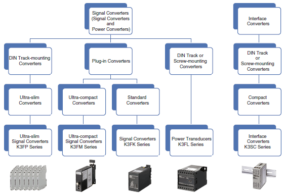
OMRON Converters are classified as shown below.
Configuration Examples for Major Converters
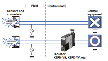
Isolators
The effects of problems in the field can be minimized by electrically isolating control equipment in a control room from problems that are caused by the environment in the field.
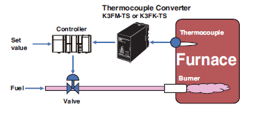
Thermocouple Converters
The temperature in a gas-fired furnace is measured with a thermocouple and converted to a normalized DC signal by passing it through a thermocouple converter, and then that signal is input into the controller. The controller can control the temperature inside the furnace by comparing the temperature to the set value and controlling a valve.
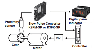
Pulse Converters
Rotary speed control can be performed by converting a rotary pulse signal from a proximity sensor to an analog signal.
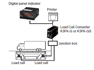
Load Cell Converters
The measurement results from a load cell can be digitally displayed on a digital panel indicator.Using the digital panel indicator’s functions, an alarm can also be output for a set threshold, in addition to displaying the measurement results.
Power Converters
Power Converters
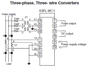
Total power can be obtained when the cumulative pulse output of a Power Converter with a cumulative pulse output (e.g., K3FL-WT[], K3FL-WN[], or K3FL-WP[]) is input to a pulse counter or other device.
A Power Converter accepts signal inputs from a potential transformer (PT) and current transformer (CT), calculates the effective power, and simultaneously outputs a normalized DC signal and cumulative pulse signal. Instantaneous power and total power can be easily displayed, which makes Power Converters important for detailed monitoring of process-specific power consumption in factories and building equipment.
Interface Converter(K3SC)
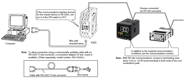
Connecting an RS-232C or USB Master Device to an RS-422/485 Slave Device
First set the same communications conditions (baud rate, stop bits, data length, and parity) for the master device, the Interface Converter, and slave devices.
Note:
1. 1-to-N connection via OMRON NT Link communications is not supported.
2. If the communications interface format for the master device is USB, obtain a commercially available USB cable and download the USB driver for the K3SC from the OMRON web site.
Connecting a USB Master Device to an RS-232C Slave Device
First set the same communications conditions (baud rate, stop bits, data length, and parity) for the master device, the Interface Converter, and slave devices.
Note: There is no isolation between the USB and RS-232C sides.


