Programmable Terminals
OMRON Programmable Terminals are easy-to-use HMIs that provide representational power, network compatibility, and powerful controller linking to support facility and machine production.
|
|
|
|
|
Classifications |
| Engineering Data | Further Information |
| Explanation of Terms | Troubleshooting |
Features and Principles of Touch Panel Methods
Touch panel methods and features are listed below. OMRON PTs use analog resistance membrane.
| Touch panel method | Acoustic pulse recognition (APR) | Surface acoustic wave (ultrasonic wave) | Capacitive (analog capacitive) | Optic (infrared) | Resistance membrane |
| Features | Detects the acoustic wave generated upon a touch or dragging. Optics and durability of pure glass. Resistant to water and dust. | Senses soft objects. Scratch-resistance and optical clarity of glass overlay. Accurate touch response using a gloved finger. | Senses the touch of a finger. Does not sense water drops, insects, and other foreign matters, reducing input errors. | Consists of LED emitters and receivers. Not affected by scratches on the touch surface. Possibility of input errors caused by parallax between the sensors and display. | Works with a touch of anything. Relatively lower durability and light transmittance due to the membrane surface. Lower production cost than other methods. |
Resistance Membrane
Two materials with transparent conductive layers (ITO) are placed with a gap between them so that transparent conductive layers are facing each other. When the touch panel is pressed down with a finger or pen and the transparent conductive layers contact, a touch input will be made. There
are spacing dots (insulators) between the top and bottom conductive layers to prevent contacts between them when the touch panel is not pressed. Resistance membrane touch panels are divided into analog types and matrix types.

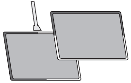
Analog resistance membrane

Transparent conductive layers are formed over the entire surface of the top and bottom layers. One of the two layers constructs the X-coordinate circuit while the other layer constructs the Y-coordinate circuit. The resistance ratio at a touched position is detected as an analog value.
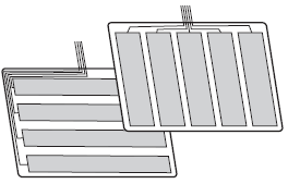
Matrix resistance membrane

Transparent conductive layers strips formed on the top and bottom layers are at right angles to each other. When the panel is touched, the position is detected in the X and Y coordinates.
| Resistance membrane touch panel | Analog | Matrix |
| Models | NA Series, NB Series, NV Series, and NS15 | NS5, NS8, NS10, NS12, and NT631C |


