Cam Positioners
|
|
|
|
|
Classifications |
| Engineering Data |
|
| Explanation of Terms | Troubleshooting |
Cam Positioner
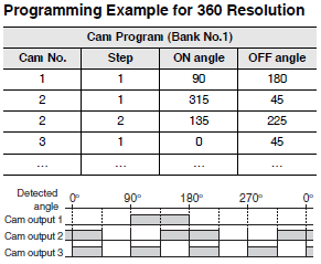
Cam Program
Data containing the ON and OFF angles for the cam output that were set by the user.
Cam Output
An output that is turned ON and OFF according to the detected angle based on the ON and OFF angles set by the user (i.e., the cam program).
Bank
A bank contains one cam program, i.e., one set of cam output settings. The cam program that is used in operation changes when the bank is changed.
Step
One combination of ON and OFF angle settings for the cam.

Cam Protection
Protection that can be set for each bank and cam so that the cam ON/OFF angle settings will not be accidentally changed or deleted.
Test Operation
A function to adjust the ON and OFF angles for cam outputs with key inputs to confirm the operation of the mechanical system without inputting external control signals.
Test operation is normally used to check the settings in the cam program when commissioning a system.
Adjustment Operation
A function to adjust the ON and OFF angles for cam outputs with key inputs during operation.
This function is normally used to adjust the ON and OFF angles during operation after system application has begun.
Origin
The point that is set as the zero point of the angle detector.
Backlash Compensation
A function to correct for looseness in the mechanical system by establishing differences in the detected angles depending on the direction of rotation. A compensation value that is equivalent to the looseness in the system can be set to align
the cam output with specific positions.

Allowable Thrust and Radial Forces
The thrust and radial forces represent the maximum vertical and horizontal forces that can be applied to a shaft. The magnitude of these forces is proportional to the service life of the product (i.e., the mechanical service life of the bearings).

Resolver
Resolution
The number of divisions in one revolution.
Allowable Resolver Speed
The maximum speed at which angle signals can be input from the angle detector. The speed is given as the maximum number of revolutions per minute. The unit is r/min.
Absolute Encoder
Resolution
The number of divisions in one revolution.
(A Gray code is output instead of a pulse.)
Response Speed
The same as the allowable Resolver speed.


