Wiring Systems
|
|
Features |
| Principles | Classifications |
| Engineering Data | Further Information |
|
|
Troubleshooting |
Connector Section Structures
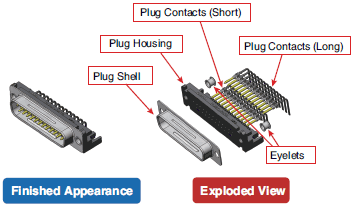
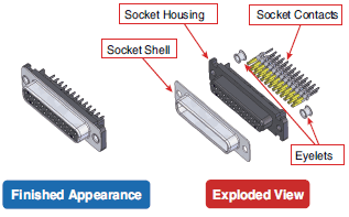
Connectors have a plug (male) side and a socket (female) side. Their structures are shown below.
Example: D-Sub Connectors
Connector Image Diagram (Plug Side)

Connector Image Diagram (Socket Side)

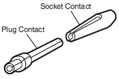
The connector contacts include the plug contacts on the plug side and the socket contacts on the socket side.

Connector Connection Methods
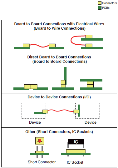
Connectors are divided into various types according to their applications and application locations.

Parts connected with connectors include wires and PCBs as described above. Typical connection methods for each are described below.
Wire Connection Methods (Typical Examples)
Crimping:
A wire connection technique in which metals are compressed to form a metal structure. The connection is made by applying high pressure to the wire from which the covering has been stripped and to the connector terminal.
IDC pressing:
A wire connection technique in which metal is compressed to form a metal structure. By pressing the wire with the covering intact against the contact section with high pressure, the wire covering is pierced through and an electrical connection is made.
Board Connection Methods (Typical Examples)
Soldering:
This method makes the connection by melting solder (a mixture of tin, lead, silver, flux, etc.) at high temperature and allowing it to flow into the connection. Industrial methods for automatic soldering include flow soldering and reflow soldering. When complying with an RoHS directive, it is necessary to use lead-free solder.
Press-fitting:
This method is used to make connections with an interference fit between the PCB terminals of connectors and the through holes in a PCB.
* A through hole is a hole for inserting a terminal into a PCB.
Cable Specifications
The cables used for connectors are mainly standard cables (F cables) or oil-resistant cables (P cables).
Standard Cables (F Cables)
UL AWM2464, 6-mm dia., 4 cores × AWG20 (0.08/110)
Robot
Fire-retardant
CL3 certified
NFPA (National Fire Protection Association) wire standard for industrial machinery for North America
PVC (polyvinyl chloride) is used.
In 2011, A cables (standard), R cables (robot), F cables (fire-retardant), and CL3 (CL3 certified cables) were all consolidated as F cables.
Oil-resistant Cables (P Cables)
6-mm dia., 4 cores × AWG20 (0.12/45)
PUR (polyurethane) is used.
Cable specifications generally specify the following.
Example: Interpreting “UL AWM2464, 6-mm dia., 4 cores × AWG20 (0.08/110)” Standard Cable
UL ...................Indicates a UL-certified part.
AWM2464 .......Specifies the rating, wire part name, and application.
6-mm dia.........Specifies the cable outer diameter.
4×AWG20 .......Specifies that there are four core wires with a gauge of AWG 20.
(0.08/110) ........Specifies that there are 110 wires with a diameter of 0.08 mm in the conductor section.
(The smaller the wire diameter and the more wires there are, the higher the bending resistance.)


