Wiring Systems
|
|
Features |
| Principles | Classifications |
| Engineering Data |
|
| Explanation of Terms | Troubleshooting |
-
 Names
Names
-
 Configurations and Structures
-
 Electrical Performance
-
 Mechanical Performance
-
 Information on Standards
Names
PCB Mounting Dimensions
Bottom View: View of PCB from solder mounting surface.
Top View: View of PCB from part mounting surface.
In the datasheets, the bottom view is given for products with DIP terminals and the top view for products with surface mounting terminals.
Triangle Mark
The position of the first terminal on the connector. (Some products have no triangle mark.)
Part Names (HSG, CNT, and Pin Clamp)
CNT (contact): Contacts for making electrical connections designed for use in multi-pole connectors.
HSG (housing): A synonym for a molded insulator that, for a connector with no shell, has the functions of holding the contacts in the correct alignment and insulating the contacts from each other and from any other conductors.
Pin Clamp: Same function as kink treatment.
The objective is to increase the strength after mounting.
Twin Contacts
A method in which contact is made at two points.

Separated Contact
A contact that can be attached to or removed from the housing.

Dummy Board
A board inserted instead of the single-row contacts when they are left empty.
Insulation Barrel
The part of a contact that crimps the insulating sheath of a wire.
Lance
The lance-like projections arranged on a contact to secure it in the housing. A synonym for locking tab.
Plugs and Sockets
Connectors are classified as plugs or sockets according to the shape of the contact section or according to the connector that has the contacts.
Plug: Same as male connector, pin header, or post.
A connector with fixed contacts.
Mates with the socket contacts to make electrical connections.
Socket: Same as female connector or receptacle.
A connector with moving contacts.
Mates with the plug contacts to make electrical connections.
Harness
A part with wires attached to connectors.
Connector Mounting Tab
A part on both ends of the connector’s housing mating section.
Used as a space for installing a screw, pin clamp, or other fixture.
Minimum Packing Unit
The minimum number packed for shipment from the factory.
Number of Pins
The number of contacts.
A synonym for pin count.
Pitch (Between Rows)
The interval between terminals in the long direction (distance between the terminal centers).
There is also a pitch between rows, which indicates the interval (distance between terminal centers) between rows of terminals in the long direction.
Through Holes
Holes into which terminals are inserted in order to connect connector terminals to the PCB wiring pattern.
Connector terminals are inserted into these holes and soldered to make the electrical connections.
A through hole sometimes indicates a hole used to connect the front and rear side wiring patterns of a PCB.
AWG
AWG is an abbreviation for American Wire Gauge. It is a conductor standard that indicates the core cross-sectional area for wires generally used in the United States.
Plating
Surface treatment that covers the surface of a metal or other material with a thin metal film (examples: gold plating or tin plating).
Coding
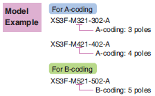
Processing performed on the housing in order to prevent incorrect insertion during connector mating.
Configurations and Structures
Standard (Perpendicular)
When perpendicular printed-wiring boards are connected, a socket straight terminal connector is connected to the motherboard (main board) and a plug right-angle terminal connector is connected to the daughterboard (sub-board).
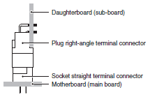
Reverse (Perpendicular)
When perpendicular printed-wiring boards are connected, a plug straight terminal connector is connected to the motherboard (main board) and a socket right-angle terminal connector is connected to the daughterboard (sub-board).

Stacking
Placing printed-wiring boards on top of each other and connecting them parallel to each other.
The distance between the stacked circuit boards is called the stacking height.
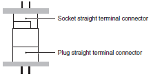
Horizontal
Connecting two printed-wiring boards so that they are horizontal to each other.

One-piece Connector
A connector that connects directly.
This term indicates a female connector that directly connects to a contact pattern on a printed-wiring board.
A card edge connector is a type of one-piece connector.
Two-piece Connector
A connector that connects indirectly.
This term indicates a type of connectors, male and female connectors, which are mounted on respective printed-wiring boards and are mated to each other to connect the PCBs.
Low Profile
A term that described a device with a low height.
Low-profile connectors are used in the following cases:
When the vertical distance between PCBs is small when the connectors are mated.
When the heights of the parts mounted on a PCB are low.
Wiping Effect
For a connector, this means that during mating, the socket contacts wipe any foreign matter off the contact surfaces of the plug contacts so that contact is made between clean surfaces.
Fine Fitting
Connecting with press fitting using OMRON’s unique terminal shape.
Solder-free Connection Section (Fine-Fit Section) Structural Diagram

The cross section has a W shape.
The two points at the bottom serve as guide rails to minimize torsion.
The two pairs of fins at the top deform to fit in the PCB through hole.
Backplane (Rack) System
A configuration in which multiple PCBs are placed in parallel with a direction intersecting the motherboard and joined by means of connectors.
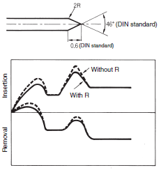
Low Insertion Force Design
A plug tip shape like that in the figure below is used to reduce the insertion force.
The plug tip shape is regulated by the DIN standards, but the insertion force can be reduced by slightly rounding between the straight section of the plug and the tip section as in the figure below.
Bus Line Connection
A form of connection in which multiple devices are connected one at a time to a single main line.
Daisy Chain
A technique for connecting peripherals or other devices with cables in which the devices are connected in series.
Sequence
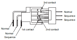
A connection structure in which live wires can be connected and disconnected because the pins are given different lengths so that when connectors are mated, the power terminals connect first and the signal terminals are connected with power already being supplied and when connectors are disconnected, the power terminals are disconnected with the signal terminals already disconnected.
Terminals that have different terminal lengths to achieve this are called sequential terminals.
Three-step Sequence
A structure that combines normal terminals and sequential terminals to give a time difference to three-step contact system.
Electrical Performance
Rated Current
A current that serves as a reference for connector use.
The rated current is normally specified according to the temperature rise limit of the connector contact section, connection section, etc.
Rated Voltage
A voltage that serves as a reference for connector use
Contact Resistance
The electrical resistance between contacts when the connectors are mated in the normal usage state.
This electrical resistance is found by supplying the specified test current and measuring the voltage at the specified contact location. Therefore, this always includes the resistance of the contact conductors. Normally, a low-level contact resistance (measurement current: 100 mA max., open voltage: 20 mV max.) is given.
Insulation Resistance
The value of the resistance to the leakage current that flows through the insulator when the specified voltage is applied between adjacent contacts on the connector or between a contact and other adjacent metal.
Dielectric Strength
The limit to the voltage between adjacent contacts on the connector or between a contact and other adjacent metal for which no insulation breakdown, flashover, or other abnormality occurs within a certain time (normally, 1 minute).
Mechanical Performance
Insertion Tolerance
The minimum number of repeated connection (insertion) and disconnection (removal) operations that a connector can withstand.
The number of operations for which the base metal is first exposed is used as a guideline.
Note:This is not the number of operations that indicates the contact resistance rise limit.
Ambient Operating Temperature Range
The ambient temperature range around the connector in which it can be used in normal condition.
(There must be no condensation at low temperatures.)
Contact Insertion Force and Contact Removal Force
The force required to connect or disconnect the plug contacts and socket contacts.
Normally, a gauge specified for the specific connector is used instead of the plug contact. For the contact insertion force, the
maximum value is specified and for the contact removal force, the minimum value is specified.
Total Insertion Force and Total Removal Force
The force required to connect or disconnect the entire plug and socket. Normally, for the total insertion force, the maximum value is specified and for the total removal force, the minimum value is specified.
Vibration
The range of mechanical vibration in which the connector satisfies its performance and characteristics requirements.
Information on Standards
VME Bus
This is a computer bus standard. It is used by many devices and standardized as ANSI/IEEE 1014-1987 by the IEC.
IEC Standards: Specifications and Mating Dimensions
The specifications and mating dimensions of M12 Round Connectors comply with IEC 61076-2-101.

Model Example
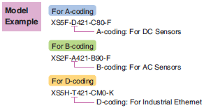
The specifications and mating dimensions of M8 Round Connectors comply with IEC 61076-2-104.
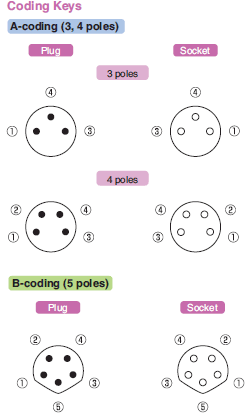
Model Example
