Power Supplies
|
|
Features |
| Principles |
|
| Engineering Data |
|
|
|
Troubleshooting |
Before Use
Purchase
External Appearance, Model, and Specifications
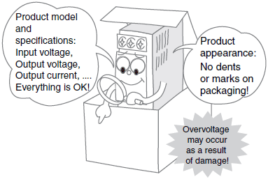
*For details, refer to External appearance and Model and specifications in the Check point column of the table of below.
Installation
Product Installation Conditions
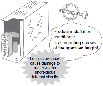
*For details, refer to Installation conditions in the Check point column of the table of below.
Installation Location
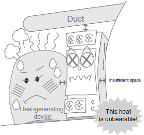
*For details, refer to Installation location in the Check point column of the table of below.
Operating Environment (1)
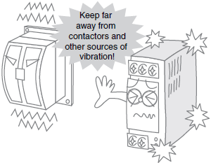
*For details, refer to Operating environment in the Check point column of the table of below.
Operating Environment (2)
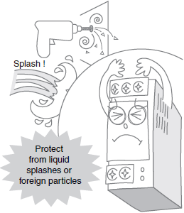
*For details, refer to Operating environment in the Check point column of the table of below.
Wiring
Input Voltage Selector Terminals
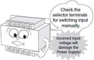
*For details, refer to Input voltage selector terminals in the Check point column of the table of below.
Input Terminals

*For details, refer to Input terminals in the Check point column of the table of below.
Terminal Wiring
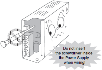
*For details, refer to Terminal wiring in the Check point column of the table of below.
Series, Parallel, and ± Output Operation
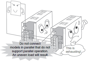
*For details, refer to Series, parallel, and ± output operation in the Check point column of the table of below.
Read the operation manual provided with the Product, and check the following points, as applicable.
| When | Check point | Details |
| Purchasing | External appearance | After purchase, make sure that the product and packaging have no dents or marks. Any internal damage may result in overvoltage depending on the location of the damage. (Stop using the product if dents, marks, or deformation is evident.) |
| Model and specifications | Make sure that the input voltage, output voltage, and output current of the Power Supply purchased meet the requirements. (The I/O specifications are provided on the model label.) | |
| Installing | Installation conditions | Be sure to use mounting screws of the specified length. Using longer screws may cause damage to the PCB, or short-circuit the internal circuits. |
| Installation location | Ensure sufficient mounting space, taking heat dissipation into consideration. | |
| Operating environment | Make sure that the ambient temperature, and vibration in the installation environment satisfy the specified levels for each product being used. (Be sure to install the Power Supply as far as possible away from contactors, which will subject the Power Supply to vibration and shock if it is located in their vicinity.) Install the Power Supply in a location in which liquid or foreign particles will not enter the Power Supply. | |
| Wiring | Input voltage selector terminals | Before turning ON the power, make sure that the voltage specifications are the same as the voltage of the device. The Power Supply is shipped with the input voltage selector terminals open (i.e., set to 200 VAC). |
| Input terminals | Wire the Power Supply inputs correctly. Connecting the AC input wires to the output terminals or voltage selector terminals will cause damage to the internal circuits. | |
| Terminal wiring | Do not subject the terminals to excessive stress by using excessive force when tightening the terminal screws. After tightening the screws to the specified torque, make sure that none of the screws is loose. Make sure that the end of the screwdriver used to tighten the screws does not mark or damage the PCB or internal parts. | |
| Connect the ground terminal to prevent electric shock. | ||
| Remote sensing terminals | Check whether remote sensing is securely connected. If remote sensing is not to be used, short-circuit using the short bar. (At shipment, these terminals are short-circuited with the short bar.) | |
| Remote control terminals | Check whether the remote control terminals are securely connected. If remote control is not to be used, short-circuit using the short bar. (At shipment, these terminals are short-circuited with the short bar.) | |
| Series, parallel, and ± output operation | Check whether series, parallel, or ±operation is supported. Refer to the wiring information in this guide. | |
| Adjusting the output voltage | Output Voltage Adjuster | Do not apply unnecessarily strong force on the Output Voltage Adjuster (V.ADJ). Doing so may damage the V.ADJ. Make sure that the end of the screwdriver used to adjust the setting does not mark or damage the PCB. |
Troubleshooting
Example 1: No Output or Delay in Output Turning ON
Turning ON for the First Time
Output Does Not Turn ON

*For details, refer to The output does not turn ON.in the Problem column of the table of below.
Delay in Output Turning ON

*For details, refer to An output delay occurs in the output turning ON. in the Problem column of the table of below.
During Operation
No Power Supply Output (Lightning Strike)
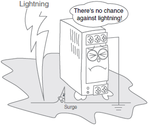
*For details, refer to Output from the Power Supply has stopped (lightning occurred) in the Problem column of the table of below.
No Power Supply Output
(Device Generating Strong, High-frequency Noise Nearby)
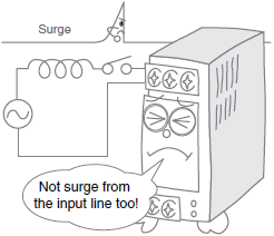
*For details, refer to Output from the Power Supply has stopped (close to source of strong, high-frequency noise). in the Problem column of the table of below.
Long-term Usage
No Power Supply Output (Fan Stopped)
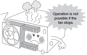
*For details, refer to Output from the Power Supply has stopped (the fan has stopped). in the Problem column of the table of below.
Low Output Power

*For details, refer to The output drops. in the Problem column of the table of below.
Example 2: Unstable Output
During Operation
Unstable Output Voltage
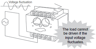
*For details, refer to The output voltage is unstable. in the Problem column of the table of below.
Low Voltage Applied to Load

*For details, refer to The voltage applied to the load is low. in the Problem column of the table of below.
Long-term Usage
Unstable Output

*For details, refer to The output is unstable. in the Problem column of the table of below.
Low Output Power

*For details, refer to The output drops. in the Problem column of the table of below.
Be sure to check the following points if the Power Supply is not operating properly before requesting repairs.
If the Power Supply still does not operate normally, contact your OMRON representative.
| Location | Problem | Details | Countermeasures |
| Dielectric strength inspection | The result of dielectric strength test is NG. | Impulse occurred damaging the Power Supply when the dielectric strength was applied or shut off using a switch or other means. | Either gradually change the applied dielectric strength using a variable resistor or apply voltage at zero cross (applied from 0 V). |
| Dielectric strength has been applied to the incorrect location. | The voltage value depends on the location at which dielectric strength is applied. Test using the dielectric strength value specific to each Power Supply. | ||
| Turning ON the power for the first time | The output does not turn ON. (・ Output voltage is low. ・ Output indicator is not lit or dim.) | The overcurrent protection function has been activated by the startup current of the load that is connected to the Power Supply, even if the current was within the Power Supply's capacity when stationary. | Use inverse L overcurrent protection characteristics or consider raising the Power Supply's capacity by one rank. |
| The Power Supply's load has exceeded the ratings, thereby activating the overcurrent protection function. | Select a Power Supply capacity that is sufficient for the load current. | ||
| The Power Supply's outputs are short-circuited. | Remove the cause of the output short-circuit. | ||
| A buzzing noise is heard when the input turns ON. | A buzzing noise can be heard when turning ON the input of models equipped with harmonic current suppression circuits due to the internal inrush current. | Models with harmonic current suppression circuits generate a noise when the input is turned ON but this is a transient noise that occurs until the internal voltage is stabilized, and does not indicate that any problem in the Power Supply. | |
| An output delay occurs in the output turning ON. | If a capacitive load (capacitor) is connected to the Power Supply's load, the inrush current on the load side will cause the output to enter the protection range when it turns ON. | If inrush current flows to the load, consider selecting a capacity that allows for the inrush current. | |
| The output voltage is high. | The adjuster setting is high. | Adjust the output voltage using the Output Voltage Adjuster (V.ADJ). | |
| The output voltage is high (caused damage to the load). | The damage to the internal parts has prevented the feedback control from performing properly. | The internal circuits are possibly damaged. Consult your OMRON representative. | |
| The output indicator turns ON but immediately goes out. | The remote sensing terminals are open. | When not using remote sensing, short-circuit terminals +V and +S, and also terminals -V and -S. The overvoltage protection function will operate, so turn OFF the input power and then turn it back ON again.  | |
| The internal control circuit has malfunctioned, thereby activating the overvoltage protection function. | Turn OFF the input power and then turn it back ON again. If the problem reoccurs, the internal circuits are possibly damaged. Consult your OMRON representative. | ||
| An electric shock is felt when touching the Power Supply. | The casing may not be properly grounded. | Connect the ground terminal to the ground. | |
| The input breaker is operating. The external fuse is broken. | The Power Supply's inrush current has tripped the breaker. | Check the inrush current of each Power Supply and check the specifications of the external fuse and breaker. (The inrush current of the Power Supply is several times to several tens of times the normal current.) | |
| The Power Supply's fuse is broken. | The internal circuit has short- circuited due to wire clippings, or other foreign particles, or mounting screws. | The internal circuits are possibly damaged. Consult your OMRON representative. | |
| White smoke was emitted from the Power Supply. | The incorrect input power is being applied. The white smoke indicates the vaporization of the electrolytic fluid in the internal electrolytic capacitor due to overvoltage. | Check the input points and input voltage of the input Power Supply again. This problem indicates that the internal circuits are damaged. Replace the Power Supply. | |
| There is no output. | A load is connected to the remote sensing terminals. | The output current cannot be received from the remote sensing terminals +S and -S. Connect the load lines to the output terminals +V and -V. Alternatively, the overvoltage protection function is operating, so turn OFF the input power and then turn it ON again. | |
| The remote control terminals are open. | When not using remote control, short-circuit the terminals +RC and -RC.  | ||
| Operation | The Power Supply's fuse is broken. | Foreign particles, liquids, condensation, or dust from the operating environment has entered the Power Supply and damaged the internal circuits. | Many holes are provided on the Product to assist with heat dissipation. Therefore, do not install the product in an environment where foreign particles, liquid, or other substance can enter the Power Supply. In this case, the internal circuits are damaged. Replace the Power Supply. |
| The Power Supply is generating high heat. | The Power Supply's installation space is too confined and does not allow sufficient heat dissipation. | The Power Supply handles a large amount of power, so heat generation occurs even with normal use. Check the installation space, Power Supply load, and ambient temperature again. Particularly if the load current exceeds the ratings for the Power Supply, change so that the load current is within the ratings. Continuing to use as is may damage the Power Supply. | |
| The Power Supply's load exceeds the ratings. | |||
| The ambient temperature is too high. | |||
| The Power Supply is emitting a noise. | The load has exceeded the ratings, activating the overcurrent protection circuit and the internal oscillatory frequency is within audible range. | When the protection circuit is operating, a vibrating sound emitting from the Power Supply may be audible. Even during normal operation, slight sound is generated by the Power Supply circuit due to the oscillator. If the oscillating sound is too loud compared with that of the same Power Supply, the internal circuits may be damaged. Consult your OMRON representative. | |
| The connected Sensor is always ON. The display on the Digital Panel Meter is erratic. The analog sensor data is erratic. | The connected Sensor has malfunctioned due to noise from the Power Supply (noise between the outputs and ground). | The Power Supply has an internal oscillator that generates noise even during normal operation. Therefore, malfunction may result depending on the Sensor used. If the Sensor malfunctions, connect a film capacitor with a capacitance of approximately 0.1 μF and a dielectric strength of 500 VDC minimum between the output terminal (+V or -V) and the ground terminal (  ). ).  | |
| Output from the Power Supply has stopped (lightning occurred) | Overvoltage is being applied to the Power Supply due to inductive impulse from the lightning. (Output may also have stopped due to the overvoltage protection function being activated.) | If overload protection is operating, turn OFF the input power and then turn it back ON again. If the output still does not recover, the internal components are possibly damaged due to the overvoltage. Replace the Power Supply. | |
| The output voltage is unstable. | Load fluctuation has activated the overcurrent protection function. | Select a Power Supply capacity that takes the load fluctuation into consideration so that the rated output current will not be exceeded. | |
| Sufficient load current cannot be supplied due to low input voltage, thereby activating the overcurrent protection function. | Use an input voltage within the allowable range. | ||
| The voltage applied to the load is unstable. | The Power Supply's output voltage has dropped due to the load's inrush current. | If an inrush current is flowing to the load, consider selecting a capacity that allows for the inrush current. | |
| The voltage applied to the load is low. | The load lines are either too thin or too long, causing a voltage drop. | Use load lines with wire diameters that are suitable for the rated output current. | |
| Output from the Power Supply has stopped. | Surge or other overvoltage has been applied externally (e.g., load) to the output side, activating overvoltage protection. | Add a varistor and diode to the source of the surge, and make sure that overvoltage is not applied to the Power Supply's outputs. | |
| The incorrect input voltage (applying 100 V when the setting is 200 V) has been applied. (If 100 V is applied when the voltage is set to 200 V, although damage will not occur immediately, damage will occur if use is continued.) | Make sure that the input voltage is the same as the voltage set using the selector terminals. The internal circuits may be damaged. Replace the Power Supply. | ||
| Output from the Power Supply has stopped (close to source of vibration or shock). | Cracks have occurred in the internal soldering due to vibration in the operating environment, preventing electrical conduction. (The vibration and shock are particularly close to the contactor.) | If vibration occurs during operation, check the installation location and reduce vibration or consider inserting vibration-proof rubber between the Power Supply and its mounting surface. | |
| Output from the Power Supply has stopped (close to source of strong, high-frequency noise). | Damage has occurred due to impulse from the input line. | If impulse occurs in the input line, separate the Power Supply's input line from the source of the impulse. If separation is not possible, connect a varistor either to the source of the noise or to the Power Supply's input terminals. Also incorporate a fuse that will provide protection if the varistor is short-circuited and damaged.  | |
| Long- term use | Output from the Power Supply has stopped (the fan has stopped). | The fan's life has expired, preventing forced cooling, and the internal temperature has risen activating overheating protection. | Perform periodic maintenance on the forced cooling fan and replace the fan promptly if any fault in the fan is found. |
| The fan bearings have been worn down due to the operating environment (e.g., dust or dirt). | Perform periodic maintenance on the forced cooling fan and make sure that there is no dust or dirt present in the operating environment. | ||
| The output is unstable. | The terminals have become loose. | Retighten the terminals to the specified torque. | |
| The output drops. | The life of the internal components has expired. | The service life of the Power Supply's built-in electrolytic capacitor depends on the ambient temperature and load rate, and its structural life depends on the operating environment (vibration, shock). Replace the Power Supply together with other Power Supplies that were purchased at the same time. | |
| Ripple noise has increased. |


