Power Supplies
|
|
Features |
| Principles |
|
| Engineering Data |
|
| Explanation of Terms |
|
Efficiency
Efficiency (%)
The efficiency indicates how much of the effective input power is converted to the output power. The Power Supply does not have 100% conversion efficiency. A portion of power becomes heat. The efficiency listed in the Power Supply datasheets are for the rated input and output. Refer to the technical data for the actual values of each load rate.
Input Conditions
The input voltage specifies the input voltage range at which the rated operations and performance can be maintained.
Values are expressed as the effective values for an AC input.
Power Factor
The Power Supply's power factor is typically approx. 0.4 to 0.6 for models without a power factor improvement circuit and approx.
0.9 to 0.95 for models with a power factor improvement circuit.
Harmonic Current Control
Harmonic currents are the frequency components that are multiples (2 to about 40) of the 50/60 Hz sine wave of the basic AC current. Most Switch-mode Power Supplies incorporate capacitors, including Power Supplies on household appliances). As a result, the input voltage sine wave is transformed into a steep input current pulse that is not a sine wave and that includes harmonics.

The power factor for devices that contain a lot of harmonic currents is low. The apparent power (VA) is larger than the actually consumed power (W), which increases the current.
If there are too many of this type of device connected, Power Supply facilities with more leeway are required.
There are standards that are designed to suppress harmonic currents in devices that are connected to public, low-voltage power grids. These include the international standard IEC 1000-3-2 and the EN 61000-3-2 standard (which mirrors the IEC 1000-3-2 standard) in the EU. These standards apply to devices with a rated input power of 75 W or higher that are connected to public, low-voltage grids.
In Japan, the Ministry of Economy, Trade and Industry undertakes activities to suppress harmonic currents and has issued the Guideline of Harmonic Reduction for Consumers Who Have High or Ultra-high Voltage Power Receiving Facilities.
When Switch-mode Power Supplies are used for industrial applications, countermeasures for harmonic currents are often implemented in the power receiving facilities of the factory or other sites. Therefore, there is little need for harmonic current control in the Switch-mode Power Supplies themselves. If you are connecting to a public, low-voltage power grid, such as a general household Power Supply, or you need to suppress harmonics from the Switch-mode Power Supply for any other reason, use a Power Supply that conforms to IEC 61000-3-2.
Input Current
Standard Switch-mode Power Supplies directly rectify AC input current. Usually, rectification is achieved using capacitor inputs and a smoothing capacitor through which a reactive current is allowed to flow. Therefore, the input current depends on the output power, input voltage, power factor, and efficiency, as follows:

Refer to the Power Supply datasheets for the efficiency.

Leakage Current
Switch-mode Power Supplies have an internal noise filter circuit that prevents switching noise from being fed back to the input lines and protects the internal circuit from external noise.
Leakage current is largely due to the current that flows through the capacitors (C1 or C2) of the input filter circuit.
Leakage current increases by the number of Power Supplies that you install. You must be careful when using more than one Power Supplies.
Inrush Current
When a Switch-mode Power Supply is turned on, a surge of current flows into the input smoothing capacitor to charge the capacitor. This current surge is called the "inrush current." The inrush current varies depending on the application timing and the presence of an inrush current protection circuit, but is usually several to several tens of times greater than the steady-state input current.

When two or more Switch-mode Power Supplies are used, the inrush current is the sum of the inrush currents for each Power Supply. Check the fusing characteristics of fuses and the operating characteristics of breakers, and select fuses and breakers so that external fuses will not burn out and breakers will not be activated by the inrush current.
Output Characteristics
The range over which the output voltage can be adjusted while maintaining specific output characteristics.
Note:
1.The output voltage can effectively be converted to a value above the specified range. When adjusting the voltage, however, check the actual output voltage and make sure it is within the specified output voltage range.
2.Make sure that the output voltage × output current does not exceed the rated output capacity and that the output current does not exceed the rated output current.
3.Do not apply unnecessarily strong force to the Output Voltage Adjuster (V.ADJ). Doing so may damage the V.ADJ.
Ripple and Noise
Since Switch-mode Power Supplies operate at high frequencies (i.e., as high as 20 kHz or more), the DC output will contain ripple and noise. The following figure shows a representative waveform for ripple and noise.

Since ripple and noise contain high-frequency components, the ground line of the oscilloscope must be shortened when making measurements. If the ground line is too long, it acts as an antenna which is influenced by radian waves and, consequently, the correct values of ripple and noise cannot be measured.
Static Input Variation Influence
The variation in the output voltage occurring when only the input voltage is changed slowly over the input range while maintaining constant output conditions.
Static Load Variation Influence
The variation in the output voltage occurring when the output current is changed slowly over a specified range while maintaining constant input conditions.
Temperature Variation Influence
The variation in the output voltage occurring when only the ambient operating temperature is changed.
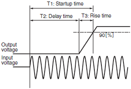
The time from when the input voltage is turned ON until the output voltage reaches 90% of the rated output voltage.
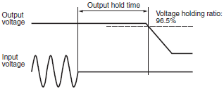
The time after the input voltage is shut off during which the output voltage maintains the voltage precision range.
Functions
Peak Current Output
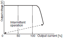
For a Switch-mode Power Supply that has overcurrent protection, the peak current that flows can be as high as the current at the overcurrent protection point.
If the current exceeds the overcurrent protection point, the output voltage will drop.
If the peak current is required, select an Switch-mode Power Supply so that the overcurrent protection point is larger than the peak current.

This protection function prevents damage to the Power Supply itself due to overcurrent (including output short-circuits). The protection function is activated and the output current is limited when the load current is greater than the overcurrent detection value (this value depends on the model).
The output voltage will also drop according to the overload (load impedance).
The drop level depends on the overload conditions and load line impedance. Continuing to use the Power Supply with an output short-circuit or in overcurrent status may cause the internal parts to be deteriorated or damaged.
The actual characteristics, such as the output current and voltage, will differ for each model. Refer to the values in the technical data and datasheets.
This protection function detects overvoltage and interruptsoutput to prevent sensors or other loads from being subjectedto excessive voltage due to failure of the Power Supply's internal recovery circuit.
To resume operation, turn OFF the input power, and wait for a fixed period of time before turning ON the input power again.
Check the datasheet for the OFF time.
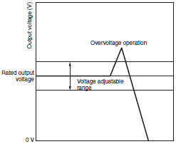
(When the overvoltage protection circuit operates, the Power Supply itself may be malfunctioning. When restarting the input power after the overvoltage protection circuit has operated, turn the input power ON with the load line disconnected and check the output voltage.)
The overvoltage protection circuit may operate if surge or other external overvoltage (e.g., from the load) is applied to the output side.
There are two application methods available when the outputs from multiple Power Supplies are connected in series:
(1)Increasing the output voltage
(2)Creating positive/negative outputs
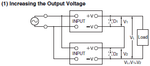
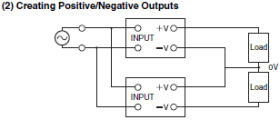
There are two application methods available when the outputs of multiple Power Supplies are connected in parallel:
(1)Increasing the output current
(2)Backing up operation
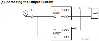

Remote sensing compensates for the voltage drop due to resistance in the wires from the Power Supply output terminals to the load.
The output voltage of the Power Supply can be turned ON and OFF from an external signal while the input voltage is being applied to the Power Supply.
The allowable range for the ambient temperature in which continuous operation is possible. The ambient temperature is the temperature that is not affected by the heat generated by the Power Supply itself.
Note:As a general rule, the ambient temperature is measured at 50 mm below the Power Supply. (There are exceptions for some models.)
Storage Temperature
The allowable range for the ambient temperature in which performance will not deteriorate due to long-term storage.
The Power Supply itself must be in a non-operational state.
The allowable ambient humidity range in which the Power Supply can be used continuously.
The vibration resistance indicates the mechanical strength against vibration when the Power Supply receives vibration due to a periodic force during transport, storage, or operation.
The datasheet gives the vibration test conditions that the Power Supply will withstand.
Use the following formula to find the acceleration from the amplitude and frequency.
Acceleration [m/s2] = 0.02 ✕ (Half amplitude [mm] ✕ 2) ✕ (Frequency [Hz])2
Acceleration [G]= Acceleration [m/s2]/9.8 [m/s2]
The shock resistance indicates the mechanical strength against shock when the Power Supply receives shock during transport, storage, or operation.
The datasheet gives the shock test conditions that the Power Supply will withstand.
Conducted Emissions
Noise voltage that enters through the Switch-mode Power Supply's AC input terminals.
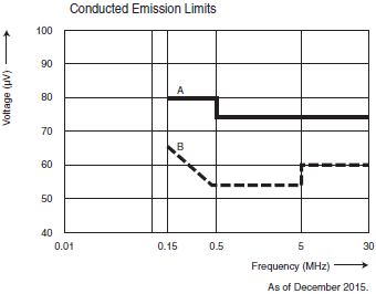
A:Devices Used in Industrial Areas and Environments
CISPR Pub. 11 Class A (ISM devices (industrial, scientific, and medical equipment))
CISPR Pub. 22 Class A (ITE devices (information technology equipment))
VCCI Class A, EN 55022 Class A
B:Devices Used in Residential Areas and Environments
CISPR Pub. 11 Class B (ISM devices (industrial, scientific, and medical equipment))
CISPR Pub. 22 Class B (ITE devices (information technology equipment))
VCCI Class B, EN 55022 Class B
Conducted Emission limits in FCC standards Part 15 and Part 18 were unified with CISPR Pub. 22 and Pub. 11 on September 9, 2002.
Radiated Emissions
The strength of the electric field (i.e., the amount of noise) that is radiated directly into the environment from the Switch-mode Power Supply.


