Solid-state Relays
No-contact relays that semiconductor is utilized, which enables high-speed and high-frequency operation. OMRON provides Solid-state Relay for enormous range of applications.
|
|
Features |
| Principles |
|
| Engineering Data | Further Information |
|
|
|
-
 SSR Internal Circuit Configuration Examples
-
 Internal Circuit Configuration Examples of SSRs for PCBs
-
 SSRs for PCBs Classified by Application and Applicable Loads
-
 MOS FET Relays
-
 Application Circuit Examples
-
 Fail-safe Concept
-
 Panel Mounting
-
 FAQs
FAQs
-
 Maintenance Guidelines
-
 Heat Radiation Designing
SSR Internal Circuit Configuration Examples
| Zero cross function | Isolation | Circuit configuration | Model |
| Yes | Photocoupler |  | G3H G3B G3F G3NA (AC input) |
| No | Phototriac |  | G3NE G3J G3F G3H G3TA-OA |
| Yes | Phototriac |  | G3PA-VD G3PE (single phase) G3NA (DC input) G3NE G3F-VD G3H-VD G3B-VD |
| Yes | Phototriac |  | G3PE-2(N) (three phases) |
| Yes | Phototriac | 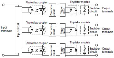 | G3PE-3(N) (three phases) |
| Yes | Photocoupler |  | G3NA-4[][]B G3PH G3PA-4[][]B |
| --- | Photocoupler |  | G3FD, G3HD-X03 G3BD G3TA-OD G3NA-D |
| Photovoltaic coupler |  | G3HD-202SN | |
| No | Photovoltaic coupler |  | G3FM |
Internal Circuit Configuration Examples of SSRs for PCBs
| Load specifications | Zero cross function | Isolation | Circuit configuration | Model |
| AC load | Yes | Photocoupler |  | G3CN, G3TB-OA |
| No | Phototriac |  | G3R, G3S, G3M, G3MC, and G3CN | |
| Yes | Phototriac |  | G3R, G3M | |
| DC load | --- | Photocoupler |  | G3SD, G3CN-D, G3RD, G3TB-OD, G3R-ID, and G3R-OD |
| AC/DC load | No | Photovoltaic coupler |  | G3DZ, G3RZ |
Note:The above circuit configurations are examples. Circuit configurations will vary depending on the model of the SSR.
SSRs for PCBs Classified by Application and Applicable Loads
1. Classification by Application
| Application | Recommended SSRs (Examples) |
| Interface These SSRs are suitable for applications in which control outputs from programmable controllers, positioning controllers, and other devices are transferred to actuators while providing isolation. In particular, the G3DZ uses a MOS FET as the output element, which means it has a low leakage current and it can be used in either an AC or DC circuit. |  |
| Office Automation, Home Automation, and Entertainment These SSRs are suitable for applications that require frequent switching, noiseless operation, and greater resistance to vibration, shock, dust, or gas than the resistance provided by mechanical relays. |  |
2. Applicable Load Examples
| Load voltage | Models | Maximum load current | Load types | Remarks | |||||
| Heater | Single- phase motor | Three- phase motor | Lamp load | Valve | Transformer * | ||||
| 110 VAC | G3R-101[], G3S-201[], G3MC-101P[] | 1 A | 0.8 A | --- | --- | 0.5 A | 0.5 A | 50 W | |
| G3R-102[], G3CN-202[], G3MC-202P[] | 2 A | 1.6 A | --- | --- | 1 A | 1 A | 100 W | ||
| 220 VAC | G3S-201[], G3R-201[], G3MC-201P[] | 1 A | 0.8 A | 15 W | 50 W | 0.5 A | 0.5 A | 100 W | |
| G3R-202[], G3CN-202[], G3MC-202P[] | 2 A | 1.6 A | 35 W | 100 W | 1 A | 1 A | 200 W | ||
| 24 VDC | G3SD-Z01[] | 1 A | 0.8 A | --- | --- | 0.5 A | 0.5 A | --- | |
| 48 VDC | G3CN-DX02[], G3RD-X02[] | 2 A | 1.6 A | --- | --- | 1 A | 1 A | --- | |
| G3CN-DX03[] | 3 A | 2.4 A | --- | --- | 1.5 A | 1.5 A | --- | ||
| 100 VDC | G3RD-101[] | 1.5 A | 0.8 A | --- | --- | 0.5 A | 0.5 A | --- | |
| 5 to 240 VAC 5 to 110 VDC | G3DZ-2R6PL | 0.6 A | --- | --- | --- | 0.5 A | 0.5 A | 60 W | |
*If the load is a transformer, do not exceed half of the normal startup power.
Note:The maximum load current of an SSR is determined by assuming that a single SSR is mounted alone and connected to a resistive load.
In actual application conditions, power supply voltage fluctuations, control panel space, and other factors can produce conditions that are more severe than those used for the testing levels.
To allow sufficient leeway for this, using values that are 20% to 30% less than the rated values is recommended.
For inductive loads, such as transformers and motors, even greater leeway is required since inrush currents occur.
MOS FET Relays
1. What Is a MOS FET Relay?
MOS FET relays are a type of SSR that are mounted on PCBs and use power MOS FETs for their output elements. They are mainly used in signal switching and connection applications.
2. Structure and Operating Principle
MOS FET relays use photodiode arrays as the light-receiving elements to operate the power MOS FETs that function as their output elements.

MOS FET relays operate according to the following principles.
(1)The LED lights when the current flows to the input side.
(2)The light from the LED is received by the photodiode array, which generates electricity to convert the light back to a voltage.
(3)This voltage passes through the control circuit to become the gate voltage to drive the MOS FET.
3. Names
MOS FET relays have a relatively short history and have been given a variety of names and brands by their manufacturers.
The table in the right shows examples of relays for signal applications (equivalent to the G3VM)
| Manufacturer | Name in catalog |
| Toshiba | Photo Relay |
| Panasonic | Photo MOS Relay |
| NEC | MOSFET Relay |
| OKI Electric Industry | Photo MOS Switch |
| Okita Works | Photo DMOS-FET Relay |
| HP | Solid-state Relay |
| OMRON | MOS FET Relay |
According to OMRON investigation in December 2015.
4. Glossary
| Term | Symbol | Description | ||
| Absolute maximum ratings | Absolute maximum ratings | -- | The maximum values that must never be exceeded even instantaneously Unless otherwise specified, these values are given at Ta = 25°C. | |
| In- put | LED forward current | IF | The rated current that can flow continuously in the LED forward direction | |
| Repetitive peak LED forward current | IFP | The rated current that can flow momentarily in the LED forward direction | ||
| LED forward current reduction rate | ΔIF/°C | The reduction rate for the current that can flow in the LED forward direction in relation to the ambient temperature | ||
| LED reverse voltage | VR | The rated reverse voltage that can be applied between the cathode and the anode | ||
| Junction temperature | Tj | The rated temperature that is allowed at the LED junction | ||
| Out- put | Load voltage | VOFF | The rated voltage that can be applied between the relay output terminals when switching the load or in the OFF state The peak voltage for AC | |
| Continuous load current | Io | The rated current that can flow between the relay output terminals in the ON state under the specified temperature conditions The peak current for AC | ||
| ON current reduction rate | ΔIo/°C | The reduction rate for the current that can flow between the relay output terminals in the ON state in relation to the ambient temperature | ||
| Pulse ON current | IOP | The rated current that can flow instantaneously between the relay output terminals in the ON state | ||
| Junction temperature | Tj | The rated temperature that is allowed at the light-receiving circuit junction | ||
| Dielectric strength between input and output | VI-O | The voltage that the isolation between the input and output can withstand | ||
| Ambient operating temperature | Ta | The ambient temperature range in which the relay can be operated without damaging the functionality of the relay | ||
| Storage temperature | Tstg | The ambient temperature range in which the relay may be stored while not operating | ||
| Soldering temperature | -- | The rated temperature at which the terminals can be soldered without damaging the functionality of the relay | ||
| Electrical charac- teristics | In- put | LED forward voltage | VF | The voltage drop between the LED anode and cathode at a certain forward current |
| Reverse current | IR | The leakage current flowing in the LED reverse direction (between cathode and anode) | ||
| Capacitance between terminals | CT | The electrostatic capacitance between the LED anode and cathode terminals | ||
| Trigger LED forward current | -- | The minimum input current that is required to change the relay output state To ensure operation of the relay, a current that is equal to or greater than the highest specified value must be used. | ||
| IFT | The minimum value of the input current IF that is required to change a normally-open output MOS FET to the ON state | |||
| IFC | The minimum value of the input current IF that is required to change a normally-closed output MOS FET to the OFF state | |||
| Release LED forward current | -- | The maximum input current that is required to release the relay output state. To ensure release of the relay, the current must be equal to or less than the minimum specified value. | ||
| IFC | The maximum value of the input current IF that must flow to change a normally-open output MOS FET to the OFF state | |||
| IFT | The maximum value of the input current IF that must flow to change a normally-closed output MOS FET to the ON state | |||
| Out- put | Maximum resistance with output ON | RON | The resistance between the relay output terminals in the specified ON state | |
| Current leakage when the relay is open | ILeak | The leakage current that flows between the relay output terminals when the specified voltage is applied in the OFF state | ||
| Capacitance between terminals | COFF | The electrostatic capacitance between the relay output terminals in the specified OFF state | ||
| Limit current | ILIM | The load current that is maintained when current limiting is activated | ||
| Capacitance between I/O terminals | CI-O | The electrostatic capacitance between the input and output terminals | ||
| Insulation resistance between I/O terminals | RI-O | The resistance between the input and output terminals at the specified voltage value | ||
| Turn-ON time | tON | The time required for the output waveform to change after the specified input LED current is applied NO relay: The time required for the output waveform to change from 100% to 10% after the input goes from OFF to ON state NC relay: The time required for the output waveform to change from 100% to 10% after the input goes from ON to OFF state | ||
| Turn-OFF time | tOFF | The time required for the output waveform to change after the specified input LED current is interrupted NO relay: The time required for the output waveform to change from 0% to 90% after the input goes from ON to OFF state NC relay: The time required for the output waveform to change from 0% to 90% after the input goes from OFF to ON state | ||
| Equivalent rise time | ERT | An indicator of the output transition characteristics for fast signals or pulse signals The ERT is expressed by the following formula, where trin is the input waveform rise time and trout is the output waveform rise time after relay transition. The lower the value, the less change there is in the signal, making for good characteristics. ERT=√(trout2-trin2) | ||
| Recom- mended operating conditions | Recommended operating conditions | -- | Indicators of the maximum ratings and electrical performances that include consideration of derating to ensure high reliability Each item is an independent condition, so it is not simultaneously satisfy several conditions. | |
| Load voltage | VDD | The recommended Load voltage that includes consideration of derating The peak voltage for AC | ||
| Operating LED forward current | IF | The recommended LED forward current that includes consideration of derating | ||
| Continuous load current | Io | The recommended load current that includes consideration of derating The peak current for AC | ||
| Operating temperature | Ta | The recommended ambient operating temperature that includes consideration of derating | ||
| Reference data | MOS FET ON-state voltage | VON | The voltage drop between the output terminals when the output MOS FET is in the ON state | |
| Relative capacity between output terminals | COFF/ COFF (0V) | The relative ratio based on the capacity between output terminals when the voltage between the output terminals is 0 V | ||
| Other terms | Current limiting | -- | When an overcurrent exceeds a certain value, this function maintains the load current between the minimum and maximum values of the limit current characteristic. Suppressing the current to a fixed value protects the relay and the circuit components connected after the relay. | |
| Low C×R | -- | An indicator of the output characteristics in applications that handle high-frequency signals, fast signals, etc. C indicates the capacity between the output terminals in the OFF state (COFF), and R indicates the resistance between the output terminals in the ON state (RON). If COFF is large, signal transition even when the relay is OFF (signal delay or isolation reduction) and the delay in the signal rise time for signal transition when the relay is ON (waveform rounding) are affected. If RON is large, signal transition loss (voltage drop and insertion loss reduction) is affected. In these applications, small COFF and RON, i.e., a low C x R characteristic, are important. | ||
Application Circuit Examples
1. Connection to Sensor
The SSR can be connected directly to a proximity sensor or photoelectric sensor.

2. Switching Control of Incandescent Lamp

3. Temperature Control of Electric Furnace

4. Forward and Reverse Operation of Single-phase Motor

Note:
1.The voltage between the load terminals of either SSR 1 or SSR 2 turned OFF is approximately twice as high as the supply voltage due to LC coupling. Be sure to apply an SSR model with a rated output voltage of at least twice the supply voltage.
For example, if forward/reverse operation is to be performed on a single-phase inductive motor with a supply voltage of 100 VAC, the SSR must have an output voltage of 200 VAC or higher.
2.Make sure that there is a time lag of 30 ms or more to switch over SW1 and SW2.
*Resistor to limit advanced phase capacitor discharge current. To select a suitable resistor, consult with the manufacturer of the motor.
5. ON/OFF Control of Three-phase Inductive Motor

6. Forward and Reverse Operation of Three-phase Motor
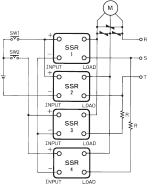
Make sure that signals input into the SSR Units are proper if the SSR Units are applied to the forward and reverse operation of a threephase motor. If SW1 and SW2 as shown in the following circuit diagram are switched over simultaneously, a phase short-circuit will result on the load side, which may damage the output elements of the SSR Units. This is because the SSR has a triac as the output element and the triac is ON until the load current becomes zero regardless of the absence of input signals into the SSR.
Therefore, make sure that there is a time lag of 30 ms or more to switch SW1 and SW2.
The SSR may be damaged due to phase short-circuiting if the SSR malfunctions with noise in the input circuit of the SSR. To protect the SSR from phase short-circuiting damage, the protective resistance R may be inserted into the circuit.
The value of the protective resistance R must be determined according to the surge withstand current of the SSR.
For example, the G3NA-220B withstands an surge current of 220 A. The value of the protective resistance R is obtained from the following formula:
R > 220 V x √2/200 A = 1.4 Ω
Considering the circuit current and ON time, insert the protective resistance into the side that reduces the current consumption.
Obtain the consumption power of the resistance from the following formula:
P = I2R x Safety factor
(I = Load current, R = Protective resistance, Safety factor = 3 to 5)
7. Transformer Tap Selection
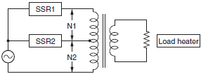
SSRs can be used to switch between transformer taps. In this case, however, be aware of voltage induced on the OFF-side SSR.
The induced voltage increases in proportion to the number of turns of the winding that is almost equivalent to the tap voltage.
See the following example. The power supply voltage is at 200 V, N1 is 100, N2 is 100, and SSR2 is ON. Then the difference in voltage between output terminals of SSR1 is at 400 V (i.e., twice as high as the power supply voltage).
8. Inrush Currents to Transformer Loads
The inrush current from a transformer load will reach its peak when the secondary side of the transformer is open, when no mutual reactance will work. It will take half a cycle of the power supply frequency for the inrush current to reach its peak, the measurement of which without an oscilloscope will be difficult.
The inrush current can be, however, estimated by measuring the DC resistance of primary side of the transformer. Due to the self-reactance of the transformer in actual operation, the actual inrush current will be less than the calculated value.
I peak = V peak/R = (√2 × V)/R
If the transformer has a DC resistance of 3 . and the load power supply voltage is 220 V, the following inrush current will flow.
I peak = (1.414 × 220)/3 = 103.7 A
The surge withstand current of OMRON's SSRs is specified on condition that the SSRs are used in nonrepetitive operation (approximately one or two operations per day). If your application requires repetitive SSR switching, use an SSR with a withstand surge current twice as high as the rated value (Ipeak).
In the above case, use the G3[][]-220[] with a surge withstand current of 207.4 A or more.
The DC resistance of the primary side of the transformer can be calculated from the withstand surge current by using the following formula.
R = V peak/I peak =(√2 ×V)/I peak
For applicable SSRs based on the DC resistance of the primary side of the transformer, refer to the tables below.
These tables list SSRs with corresponding surge withstand current conditions. When you use SSRs in actual applications, however, check the steady-state currents of the transformers satisfy the rated current requirement of each SSR.
SSR Rated Current

The underlined two digits refer to the rated current (i.e., 40A in the case of the above model).
Three digits may be used for the G3PH only.
G3PH:
G3PH-[]075B = 75 A
G3PH-[]150 = 150 A
Condition 1:
The ambient temperature of the SSR (the temperature inside the panel) is within the rated value specified.
Condition 2:
The right heat sink is provided to the SSR.
Load Power Supply Voltage of 100 V
| Transformer DC resistance (Ω) | Inrush current (A) | SSR's surge withstand current (A) | Applicable SSR | |||
| G3P[] | G3NA | G3NE | G3PH | |||
| 4.8 min. | 30 | 60 | --- | -205[] | -205[] | --- |
| 1.9 to 4.7 | 75 | 150 | -210[] -215[] | -210[] | -210[] | --- |
| 1.3 to 1.8 | 110 | 220 | -220[] -225[] | -220[] | -220[] | --- |
| 0.65 to 1.2 | 220 | 440 | -235[] -240[] -245[] -260[] | -240[] | --- | --- |
| 0.36 to 0.64 | 400 | 800 | --- | --- | --- | 2075[] |
| 0.16 to 0.35 | 900 | 1,800 | --- | --- | --- | 2150[] |
Load Power Supply Voltage of 110 V
| Transformer DC resistance (Ω) | Inrush current (A) | SSR's surge withstand current (A) | Applicable SSR | |||
| G3P[] | G3NA | G3NE | G3PH | |||
| 5.2 min. | 30 | 60 | --- | -205[] | -205[] | --- |
| 2.1 to 5.1 | 75 | 150 | -210[] -215[] | -210[] | -210[] | --- |
| 1.5 to 2.0 | 110 | 220 | -220[] -225[] | -220[] | -220[] | --- |
| 0.71 to 1.4 | 220 | 440 | -235[] -240[] -245[] -260[] | -240[] | --- | --- |
| 0.39 to 0.70 | 400 | 800 | --- | --- | --- | 2075[] |
| 0.18 to 0.38 | 900 | 1,800 | --- | --- | --- | 2150[] |
Load Power Supply Voltage of 120 V
| Transformer DC resistance (Ω) | Inrush current (A) | SSR's surge withstand current (A) | Applicable SSR | |||
| G3P[] | G3NA | G3NE | G3PH | |||
| 5.7 min. | 30 | 60 | --- | -205[] | -205[] | --- |
| 2.3 to 5.6 | 75 | 150 | -210[] -215[] | -210[] | -210[] | --- |
| 1.6 to 2.2 | 110 | 220 | -220[] -225[] | -220[] | -220[] | --- |
| 0.78 to 1.5 | 220 | 440 | -235[] -240[] -245[] -260[] | -240[] | --- | --- |
| 0.43 to 0.77 | 400 | 800 | --- | --- | --- | 2075[] |
| 0.19 to 0.42 | 900 | 1,800 | --- | --- | --- | 2150[] |
Load Power Supply Voltage of 200 V
| Transformer DC resistance (Ω) | Inrush current (A) | SSR's surge withstand current (A) | Applicable SSR | |||
| G3P[] | G3NA | G3NE | G3PH | |||
| 9.5 min. | 30 | 60 | --- | -205[] | -205[] | --- |
| 3.8 to 9.4 | 75 | 150 | -210[] -215[] | -210[] | -210[] | --- |
| 2.6 to 3.7 | 110 | 220 | -220[] -225[] | -220[] | -220[] | --- |
| 1.3 to 2.5 | 220 | 440 | -235[] -240[] -245[] -260[] | -240[] | --- | --- |
| 0.71 to 1.2 | 400 | 800 | --- | --- | --- | 2075[] |
| 0.32 to 0.70 | 900 | 1,800 | --- | --- | --- | 2150[] |
Load Power Supply Voltage of 220 V
| Transformer DC resistance (Ω) | Inrush current (A) | SSR's surge withstand current (A) | Applicable SSR | |||
| G3P[] | G3NA | G3NE | G3PH | |||
| 10.4 min. | 30 | 60 | --- | -205[] | -205[] | --- |
| 4.2 to 10.3 | 75 | 150 | -210[] -215[] | -210[] | -210[] | --- |
| 2.9 to 4.1 | 110 | 220 | -220[] -225[] | -220[] | -220[] | --- |
| 1.5 to 2.8 | 220 | 440 | -235[] -240[] -245[] -260[] | -240[] | --- | --- |
| 0.78 to 1.4 | 400 | 800 | --- | --- | --- | 2075[] |
| 0.35 to 0.77 | 900 | 1,800 | --- | --- | --- | 2150[] |
Load Power Supply Voltage of 240 V
| Transformer DC resistance (Ω) | Inrush current (A) | SSR's surge withstand current (A) | Applicable SSR | |||
| G3P[] | G3NA | G3NE | G3PH | |||
| 11.4 min. | 30 | 60 | --- | -205[] | -205[] | --- |
| 4.6 to 11.3 | 75 | 150 | -210[] -215[] | -210[] | -210[] | --- |
| 3.1 to 4.5 | 110 | 220 | -220[] -225[] | -220[] | -220[] | --- |
| 1.6 to 3.0 | 220 | 440 | -235[] -240[] -245[] -260[] | -240[] | --- | --- |
| 0.85 to 1.5 | 400 | 800 | --- | --- | --- | 2075[] |
| 0.38 to 0.84 | 900 | 1,800 | --- | --- | --- | 2150[] |
Load Power Supply Voltage of 400 V
| Transformer DC resistance (Ω) | Inrush current (A) | SSR's surge withstand current (A) | Applicable SSR | |||
| G3P[] | G3NA | G3NE | G3PH | |||
| 7.6 min. | 75 | 150 | --- | -410[] | --- | --- |
| 5.2 to 7.5 | 110 | 220 | -420[] -430[] | -420[] | --- | --- |
| 2.6 to 5.1 | 220 | 440 | -435[] -445[] | --- | --- | --- |
| 1.5 to 2.5 | 400 | 800 | --- | --- | --- | -4075[] |
| 0.63 to 1.4 | 900 | 1,800 | --- | --- | --- | -4150[] |
Load Power Supply Voltage of 440 V
| Transformer DC resistance (Ω) | Inrush current (A) | SSR's surge withstand current (A) | Applicable SSR | |||
| G3P[] | G3NA | G3NE | G3PH | |||
| 8.3 min. | 75 | 150 | --- | -410[] | --- | --- |
| 5.7 to 8.2 | 110 | 220 | -420[] -430[] | -420[] | --- | --- |
| 2.9 to 5.6 | 220 | 440 | -435[] -445[] | --- | --- | --- |
| 1.6 to 2.8 | 400 | 800 | --- | --- | --- | -4075[] |
| 0.70 to 1.5 | 900 | 1,800 | --- | --- | --- | -4150[] |
Load Power Supply Voltage of 480 V
| Transformer DC resistance (Ω) | Inrush current (A) | SSR's surge withstand current (A) | Applicable SSR | |||
| G3P[] | G3NA | G3NE | G3PH | |||
| 9.1 min. | 75 | 150 | --- | -410[] | --- | --- |
| 6.2 to 9.0 | 110 | 220 | -420[] -430[] | -420[] | --- | --- |
| 3.1 to 6.1 | 220 | 440 | -450[] | --- | --- | --- |
Fail-safe Concept
1. Error Mode
The SSR is an optimum relay for high-frequency switching and high-speed switching, but misuse or mishandling of the SSR may damage the elements and cause other problems.
The SSR consists of semiconductor elements, and will break down if these elements are damaged by surge voltage or overcurrent. Most faults associated with the elements are short-circuit malfunctions, whereby the load cannot be turned OFF.
Therefore, to provide a fail-safe measure for a control circuit using an SSR, design a circuit in which a contactor or circuit breaker on the load power supply side will turn OFF the load when the SSR causes an error. Do not design a circuit that turns OFF the load power supply only with the SSR. For example, if the SSR causes a half-wave error in a circuit in which an AC motor is connected as a load, DC energizing may cause overcurrent to flow through the motor, thus burning the motor. To prevent this from occurring, design a circuit in which a circuit breaker stops overcurrent to the motor.
| Location | Cause | Result |
| Input area | Overvoltage | Input element damage |
| Output area | Overvoltage | Output element damage |
| Overcurrent | ||
| Whole Unit | Ambient temperature exceeding maximum | Output element damage |
| Poor heat radiation |
2. Overcurrent Protection
A short-circuit current or an overcurrent flowing through the load of the SSR will damage the output element of the SSR.
Connect a quick-break fuse in series with the load as an overcurrent protection measure.
Design a circuit so that the protection coordination conditions for the quick-break fuse satisfy the relationship between the SSR surge resistance (IS), quick-break fuse current-limiting feature (IF), and the load inrush current (IL), shown in the following chart.

3. Operation Indicator
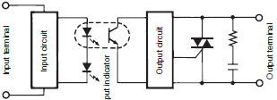
The operation indicator turns ON when current flows through the input circuit. It does not indicate that the output element is ON.
Heat Radiation Designing
1. SSR Heat Radiation
Triacs, thyristors, and power transistors are semiconductors that can be used for an SSR output circuit.
These semiconductors have a residual voltage internally when the SSR is turned ON. This is called output-ON voltage drop. If the SSR has a load current, the Joule heating of the SSR will result consequently. The heating value P (W) is obtained from the following formula.
Heating value P (W) = Output-ON voltage drop (V) × Carry current (A)
For example, if a load current of 8 A flows from the G3NA-210B, the following heating value will be obtained:
P = 1.6 V × 8 A = 12.8 W
If the SSR employs power MOS FET for SSR output, the heating value is calculated from the ON-state resistance of the power MOS FET instead.
In that case, the heating value P (W) can be calculated with the following formula:
P (W) = Load current2 (A) × ON-state resistance (Ω)
If the G3RZ is used with a load current of 0.5 A, the following heating value will be obtained:
P (W) = 0.52 A × 2.4 Ω = 0.6 W
The ON-state resistance of a power MOS FET increases with an increase in the junction temperature of a power MOS FET.
Therefore, the ON-state resistance varies while the SSR is in operation. If the load current is 80% of the load current or higher, as a simple method, the ON-state resistance will be multiplied by 1.5.
P (W) = 12 A × 2.4 Ω × 1.5 = 3.6 W
The SSR in usual operation switches a current of approximately 5 A with no heat sink used. If the SSR must switch a higher current, a heat sink will be required. The higher the load current is, the larger the heat sink size will be. If the switching current is 10 A or more, the size of the SSR with a heat sink will exceed a single mechanical relay.
This is a disadvantage of SSRs in terms of circuit downsizing.
2. Heat Sink Selection
SSR models with no heat sinks (i.e., the G3NA, G3NE, and three-phase G3PE) need external heat sinks. When using any of these SSRs, select the ideal combination of the SSR and heat sink according to the load current.
The following combinations are ideal, for example.
G3NA-220B: Y92B-N100,
G3NE-210T(L): Y92B-N50,
G3PE-235B-3H: Y92B-P200
A Commercially available heat sink equivalent to an OMRON-made one can be used, on conditoin that the thermal resistance of the heat sink is lower than that of the OMRON-made one.
For example, the Y92B-N100 has a thermal resistance of 1.63°C/W.
If the thermal resistance of the standard heat sink is lower than this value (i.e., 1.5°C/W, for example), the standard heat sink can be used for the G3NA-220B.
Thermal resistance indicates a temperature rise per unit (W). The smaller the value is, the higher the efficiency of heat radiation will be.
3. Calculating Heat Sink Area
An SSR with an external heat sink can be directly mounted to control panels under the following conditions.
If the heat sink is made of steel used for standard panels, do not apply a current as high as or higher than 10 A, because the heat conductivity of steel is less than that of aluminum. Heat conductivity (in units of W・m・°C) varies with the material as described below.
Steel: 20 to 50
Aluminum: 150 to 220
The use of an aluminum-made heat sink is recommended
if the SSR is directly mounted to control panels. Refer to the data sheet of the SSR for the required heat sink area.
Apply heat-dissipation silicone grease (e.g., the YG6260 from Momentive Performance Materials or the G746 from Shin-Etsu Silicones) or attach a heat conductive sheet between the SSR and heat sink. There will be a space between the SSR and heat sink attached to the SSR.
Therefore, the generated heat of the SSR cannot be radiated properly without the grease. As a result, the SSR may be overheated and damaged or deteriorated.
The heat dissipation capacity of a heat conduction sheet is generally inferior to that of silicone grease. If a heat conduction sheet is used, reduce the load current by approximately 10% from the Load Current vs. Ambient Temperature Characteristics graph.
4. Control Panel Heat Radiation Designing
Control equipment using semiconductors will generate heat, regardless of whether SSRs are used or not. The failure rate of semiconductors greatly increases when the ambient temperature rises. It is said that the failure rate of semiconductors will be doubled when the temperature rises 10°C (Arrhenius model).
Therefore, it is absolutely necessary to suppress the interior temperature rise of the control panel in order to ensure the long, reliable operation of the control equipment.
Heat-radiating devices in a wide variety exists in the control panel. As a matter of course, it is necessary to consider the total temperature rise as well as local temperature rise of the control panel. The following description provides information on the total heat radiation designing of the control panel.
As shown below, the heat conductivity Q will be obtained from the following formula, provided that th and tc are the temperature of the hot fluid and that of the cool fluid separated by the fixed wall.
Q = k (th - tc) A
Where, k is an overall heat transfer coefficient (W/m2°C).
This formula is called a formula of overall heat transfer.
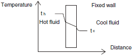
When this formula is applicable to the heat conductivity of the control panel under the following conditions, the heat conductivity Q will be obtained as shown below.
Average rate of overall heat transfer of control panel: k (W/m2°C)
Internal temperature of control panel: Th (°C)
Ambient temperature: Tc (°C)
Surface area of control panel: S (m2)
Q = k × (Th - Tc) × S
The required cooling capacity is obtained from the following formula.
Desired internal temperature of control panel: Th (°C)
Total internal heat radiation of control panel: P1 (W)
Required cooling capacity: P2 (W)
P2 = P1 - k × (Th - Tc) × S
The overall heat transfer coefficient k of a standard fixed wall in a place with natural air ventilation will be 4 to 12 (W/m2°C).
In the case of a standard control panel with no cooling fan, it is an empirically known fact that a coefficient of 4 to 6 (W/m2°C) is practically applicable. Based on this, the required cooling capacity of the control panel is obtained as shown below.
Example
Desired internal temperature of control panel: 40°C
Ambient temperature: 30°C
Control panel size 2.5 × 2 × 0.5 m (W × H × D)
Self-sustained control panel (with the bottom area excluded from the calculation of the surface area)
SSRs: 20 G3PA-240B Units in continuous operation at 30 A.
Total heat radiation of all control devices except SSRs: 500 W
Total heat radiation of control panel: P1
P1 = Output-ON voltage drop 1.6 V × Load current 30 A × 20 SSRs + Total heat radiation of all control devices except SSRs
= 960 W + 500 W = 1460 W
Heat radiation from control panel: Q2
Q2 = Rate of overall heat transfer 5 × (40°C − 30°C) × (2.5 m × 2 m × 2 + 0.5m × 2 m × 2 + 2.5 m × 0.5 m)
= 662.5 W
Therefore, the required cooling capacity P2 will be obtained from the following formula:
P2 = 1,460 − 663 = 797 W
Therefore, the heat radiation from the surface of the control panel is insufficient. More than a heat quantity of 797 W needs to be radiated outside the control panel.
Usually, a ventilation fan with a required capacity will be installed. If the fan is not sufficient, an air conditioner for the control panel will be installed. The air conditioner is ideal for the long-time operation of the control panel because it will effectively dehumidify the interior of the control panel and eliminate dust gathering in the control panel.
Axial-flow fan: OMRON's R87B, R87F, and R87T Series
Air conditioner for control panel: Apiste's ENC Series
5. Types of Cooling Device
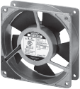
Axial-flow Fans (for Ventilation)
These products are used for normal types of cooling and ventilation.
OMRON's Axial-flow Fan lineup includes the R87F and R87T Series.
Heat Exchangers
Heat exchangers dissipate the heat inside control panels along heat pipes. Using a heat exchanger enables the inside and outside of the control panel to be mutually isolated, allowing use in locations subject to dust or oil mist.
Note:OMRON does not produce heat exchangers.

Air Conditioners for Control Panels
Not only do air conditioners offer the highest cooling capacity, they also offer resistance to dust and humidity by mutually isolating the inside and outside of the control panel.
Note:OMRON does not produce air conditioners for control panels.

Panel Mounting
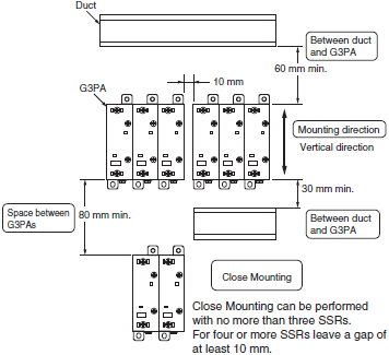
If SSRs are mounted inside an enclosed panel, the radiated heat of the SSR will stay inside, thus not only dropping the carrycurrent capacity of the SSRs but also adversely affecting other electronic device mounted inside. Open some ventilation holes on the upper and lower sides of the control panel before use. The following illustrations provide a recommended mounting example of G3PA Units. They provide only a rough guide and so be sure to confirm operating conditions using the procedure detailed in 4. Confirmation after Installation of below.
1. SSR Mounting Pitch
Panel Mounting
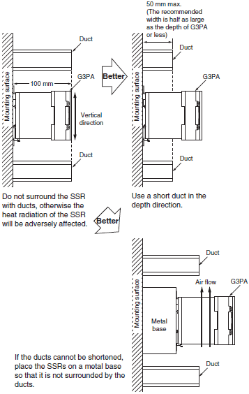
2. Relationship between SSRs and Ducts
Duct Depth
3. Ventilation
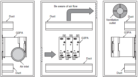
If the air inlet or air outlet has a filter, clean the filter regularly to prevent it from clogging and ensure an efficient flow of air.
Do not locate any objects around the air inlet or air outlet, or otherwise the objects may obstruct the proper ventilation of the control panel.
A heat exchanger, if used, should be located in front of the G3PA Units to ensure the efficiency of the heat exchanger.
4. Confirmation after Installation
The above conditions are typical examples confirmed by OMRON. The application environment may affect conditions and ultimately the ambient temperature must be measured under power application to confirm that the load currentambient temperature ratings are satisfied for each model.
Ambient Temperature Measurement Conditions
(1)Measure the ambient temperature under the power application conditions that will produce the highest temperature in the control panel and after the ambient temperature has become saturated.
(2)Refer to Figure 1 for the measurement position. If there is a duct or other equipment within the measurement distance of 100 mm, refer to Figure 2. If the side temperature cannot be measured, refer to Figure 3.

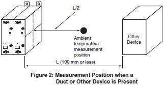

(3)If more than one row of SSRs are mounted in the control panel, measure the ambient temperature of each row, and use the position with the highest temperature.
Consult your OMRON dealer, however, if the measurement conditions are different from those given above.
Definition of Ambient Temperature
SSRs basically dissipate heat by natural convection.
Therefore, the ambient temperature is the temperature of the air that dissipates the heat of the SSR.
FAQs
Structures and Functions of SSRs
What is the difference in switching with a thyristor and a triac?
There is no difference between them as long as resistive loads are switched. For inductive loads, however, thyristors are superior to triacs due to the inverse parallel connection of the thyristors.
For the switching element, an SSR uses either a triac or a pair of thyristors connected in an inverse parallel connection.
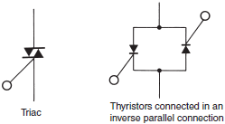
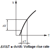
There is a difference between thyristors and triacs in response time to rapid voltage rises or drops.
This difference is expressed by dv/dt (V/μs). This value of thyristors is larger than that of triacs.
Triacs can switch inductive motor loads that are as high as 3.7 kW.
Furthermore, a single triac can be the functional equivalent of a pair of thyristors connected in an inverse parallel connection and can thus be used to contribute to downsizing SSRs.
Note:dv/dt = Voltage rise rate.
| Resistive load | Inductive load | |||
| 40 A max. | Over 40 A | 3.7 kW max. | Over 3.7 kW | |
| Triac | OK | OK | OK | Not as good |
| Two thyristors | OK | OK | OK | OK |
What is silicone grease?
Special silicone grease is used to aid heat dissipation.
The heat conduction of this special silicone grease is five to ten times higher than that of standard silicone grease.
This special silicone grease is used to fill the space between a heat-radiating part, such as an SSR, and the heat sink to improve the heat conduction of the SSR.
Unless special silicone grease is applied, the generated heat of the SSR will not be radiated properly. As a result, the SSR may break or deteriorate due to overheating.
Available Silicone Grease Products for Heat Dissipation
Momentive Performance Materials: YG6260
Shin-Etsu Silicones: G746, G747
What is the zero cross function?
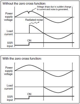
The zero cross function turns ON the SSR when the AC load voltage is close to 0 V, thus suppressing the noise generation of the load current when the load current rises quickly.
The generated noise will be partly imposed on the power line and the rest will be released in the air. The zero cross function effectively suppresses both noise paths.
(A high inrush current will flow when the lamp is turned ON, for example. When the zero cross function is used, the load current always starts from a point close to 0 V. This will suppress the inrush current more than SSRs without the zero cross function.)
What is the non-repetitive surge current?
The datasheet of an SSR gives the non-repetitive surge withstand current of the SSR. The concept of the surge withstand current of an SSR is the same as the absolute maximum rating of an element. If the surge current exceeds the surge withstand current even once, the SSR will be destroyed. Therefore, check that the maximum surge current of the SSR in normal ON/OFF operation is half of the surge withstand current. Unlike mechanical relays that may result in contact abrasion, the SSR will provide good performance as long as the surge current is no higher than half of the surge withstand current. If the SSR is in continuous ON/OFF operation and a current exceeding the rated value flows frequently, however, the SSR may overheat and a malfunction may result.
Check that the SSR is operated with no overheating.
Roughly speaking, surge currents that are less than the non-repetitive surge current and greater than the repetitive surge current can be withstood once or twice a day (e.g., when power is supplied to devices once a day).
G3NE-220T

Connections and Circuits for SSRs
Is it possible to connect Solid-state Relays for outputs in parallel (OR circuit)?
Yes, it is. SSRs are connected in parallel mainly to prevent open circuit failures. Usually, only one of the SSR is turned ON due to the difference in output ON voltage drop between the SSRs.
Therefore, it is not possible to increase the load current by connecting the SSRs in parallel. If an ON-state SSR is open in operation, the other SSR will turn ON when the voltage is applied, thus maintaining the switching operation of the load.
Do not connect two or more SSRs in parallel to drive a load exceeding the capacity each SSRs.
The SSRs may fail to operate.

Is it possible to connect Solid-state Relay for AC loads in series (AND circuit)?
Yes, it is. SSRs are connected in series mainly to prevent short circuit failures. Each SSR connected in series shares the burden of the surge voltage. The overvoltage is divided among the SSRs, reducing the load on each.
A high operating voltage, however, cannot be applied to the SSRs connected in series. The reason is that the SSRs cannot share the burden of the load voltage due to the difference between the SSRs in operating time and reset time when the load is switched.
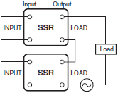
Is it possible to connect two 200-VAC SSRs in series to a 400-VAC load?
No, it is not. The two SSRs are slightly different to each other in operate time. Therefore, 400 VAC will be applied instantaneously on the SSR with a longer operate time.
What need to be done for surge absorption elements for SSRs for DC loads?
Output Noise Surge Countermeasures for SSRs for DC Load Switching
When an inductive load, such as a solenoid or electromagnetic valve, is connected, connect a diode that prevents counter-electromotive force. If the counter-electromotive force exceeds the withstand voltage of the SSR output element, it could result in damage to the SSR output element. To prevent this, insert the element parallel to the load, as shown in the following diagram and table.

As an absorption element, the diode is the most effective element to suppress counter-electromotive force. The release time for the solenoid or electromagnetic valve will, however, increase. Be sure you check the circuit before using it. To shorten the time, connect a Zener diode and a regular diode in series. The release time will be shortened at the same rate that the Zener voltage (Vz) of the Zener diode is increased.
Table 1. Absorption Element Example
| Absorption element |  |  |  |  |
| Diode | Diode + Zener diode | Varistor | CR | |
| Effective ness | Most effective | Most effective | Somewhat effective | Ineffective |

Reference
(1)Selecting a Diode
Withstand voltage = VRM ≥ Power supply voltage × 2
Forward current = IF ≥ load current
(2)Selecting a Zener Diode
Zener voltage = Vz < (Voltage between SSR's collector and emitter) * − (Power supply voltage + 2 V)
Zener surge power = PRSM > Vz × Load current × Safety factor (2 to 3)
Note:When the Zener voltage is increased (VZ), the Zener diode capacity (PRSM) is also increased.
Mounting Methods for SSRs
Does an SSR have a mounting direction?
An SSR consists of semiconductor elements.
Therefore, unlike mechanical relays that incorporate movable parts, gravity changes have no influence on the characteristics of the SSR.
Changes in the heat radiation of an SSR may, however, limit the carry current of the SSR. An SSR should be mounted vertically. If the SSR has to be mounted horizontally, check with the SSR's datasheet. If there is no data available for the SSR, use with a load current at least 30% lower than the rated load current.
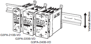

Vertical mounting
Mount the SSR vertically.

Flat Mounting
The SSR may be mounted on a flat surface, provided that the load current applied is 30% lower than the rated load current.
What precautions are required for close mounting?
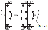
In the case of close mounting of SSRs, check the relevant data in the SSR datasheet. If there is no data, check that the applied load current is 70% of the rated load current. A 100% load current can be applied if groups of three SSRs are mounted in a single row with a space of 10 mm between adjacent groups. If the SSRs are mounted in two or more rows, it is necessary to confirm the temperature rise of the SSR separately. For close mounting of SSRs with heat sinks, reduce the load current to 80% of the rated load current. Refer to the SSR’s datasheet for details.
G3PA
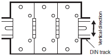
For close mounting of two or three SSRs, limit the load current to 80% or less.
G3PE
Close Mounting (3 or 8 SSRs)
G3PE-215B
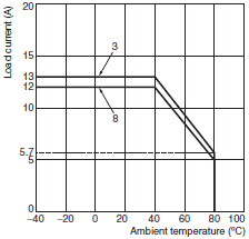
G3PE-225B

Close Mounting Example
Failure Examples and Safety Precautions for SSRs
We think an SSR is faulty. Can a voltage tester be used to check an SSR to see if current is flowing?
No, that is not possible.
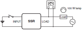
The voltage and current in the tester's internal circuits are too low to check the operation of the semiconductor element in the SSR (a triac or thyristor). The SSR can be tested as described below if a load is connected.
Testing Method
Connect a load and power supply, and check the voltage of the load terminals with the input ON and OFF. The output voltage will be close to the load power supply voltage with the SSR turned OFF. The voltage will drop to approximately 1 V with the SSR turned ON.
This is more clearly checked if the dummy load is a lamp with an output of about 100 W. (However, lamps that have capacities within the rated ranges of the SSRs must be used.)
What kind of failure do SSRs have most frequently?
OMRON's data indicates that most failures are caused by overvoltage or overcurrent as a result of the shortcircuiting of SSRs. This data is based on SSR output conditions, which include those resulting from the open or short circuit failures on the input side.
| Failure | Load condition | |
| Input | Short | Does not turn ON. |
| Open | ||
| Output | Output triac short circuit (80% of failures) | Does not turn OFF. |
| Output triac open circuit (20% of failures) | Does not turn ON. |
What precautions are necessary for forward/reverse operation of the singlephase motor?
Refer the following table for the protection of capacitor motors driven by SSRs.
| Single-phase 100 V | Load current of recommended SSR | Protection of motor in forward/ reverse operation |
| 25 W | AC 2 to 3 A | R = 6 Ω, 10 W |
| 40 W | ||
| 60 W | AC 5 A | R = 4 Ω, 20 W |
| 90 W | R = 3 Ω, 40 to 50 W |
| Single-phase 200 V | Load current of recommended SSR | Protection of motor in forward/ reverse operation |
| 25 W | AC 2 to 3 A | R = 12 Ω, 10 W |
| 40 W | ||
| 60 W | AC 5 A | R = 12 Ω, 20 W |
| 90 W | R = 8 Ω, 40 W |
Precautions for Forward/Reverse Operation
(1)In the following circuit, if SSR1 and SSR2 are turned ON simultaneously, the discharge current, i, of the capacitor may damage the SSRs. Therefore, make sure that there is a time lag of 30 ms or more to switch SW1 and SW2.
If malfunction of the SSRs is possible due to external noise or the counter-electromotive force of the motor, connect R to suppress discharge current i in series with either SSR1 or SSR2, whichever is less frequently used. A CR absorber (consisting of 0.1-μF capacitor withstanding 630 V and 22-Ω resistor withstanding 2 W) can be connected in parallel to each SSR to suppress the malfunctioning of the SSRs.
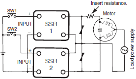
(2)When the motor is in forward/reverse operation, a voltage that is twice as high as the power supply voltage may be applied on an SSR that is OFF due to the LC resonance of the motor.
When you select an SSR, be careful that this voltage does not exceed the rated load voltage of the SSR. (It is necessary to determine whether use is possible by measuring the actual voltage applied to the SSR on the OFF side.)
Relays with the Same Shapes: Power MOS FET Relays
What are the differences between SSRs and power MOS FET relays?
(1)There are SSRs for DC loads and SSRs for AC loads.
SSR for DC Loads (e.g., G3HD-X03)

SSR for AC Loads (e.g., G3H)

(2)The leakage current for power MOS FET relays is small compared to that for SSRs.
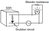
SSRs
The lamp (see below) is faintly light by the leakage current. A bleeder resistance is added to prevent this.
With SSRs, a snubber circuit is required to protect the output element.
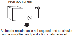
Power MOS FET Relays
The leakage current is very small (10 μA max.) and so the lamp does not light. This is because a snubber circuit is not required to protect the MOS FET output element. A varistor is used to protect the MOS FET.
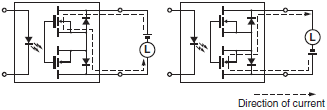
Why can MOS FET relays be used for both AC and DC loads?
With power MOS FET relays, because 2 MOS FET relays are connected in series in the way shown on the right, the load power supply can be connected in either direction. Also, because power MOS FET elements have a high dielectric strength, they can be used for AC loads, where the polarity changes every cycle.
What kind of applications can power MOS FET relays be used for?
(1)Applications where it is not known whether the load connected to the relay is AC or DC.
Example: Alarm output of robot controller.
(2)Applications with high-frequency switching of loads, such as for solenoid valves with internally, fully rectified waves, where the relay (e.g., G2R) has to be replaced frequently.
Power MOS FET relays have a longer lifetime than other relays and so the replacement frequency is less.
The terminal arrangement of the G3RZ is compatible with that of the G2R-1A-S, so these models can be exchanged.
Note:Confirm the type of input voltage, polarity, and output capacity before application.
(3)Applications with high-voltage DC loads. In order to switch a 100-VDC, 1-A load with a relay, an MM2XP or equivalent is required. With the G3RZ power MOS FET relay, however, switching at this size is possible.
(4)Applications where SSRs are used with a bleeder resistance. The leakage current for power MOS FET relays is very small (10 μA max.) and so a bleeder resistance is not required.
Maintenance Guidelines
Unlike standard relays, an SSR uses a semiconductor to switch a circuit and do not contain mechanical contacts. Furthermore, signal transfer is handled by electronic circuits, so there are no moving parts to cause mechanical friction. Therefore, to determine the life expectancy of an SSR, you must consider not only the life expectancy of the elements used but also the deterioration of soldered points and the materials of which the SSR is made.
OMRON generally considers the life expectancy of an SSR to be the point on the bathtub curve where the failure rate begins to rise and enters the wear-out failure period (for an SSR, this is the period when deterioration begins), which is approximately 10 years, although it will depend on the application environment.
Bathtub Curve for Electronic Components and Devices
Electronic components and electronic devices all experience characteristic changes, such as the deterioration of the materials they are composed of and their joints or reduced LED light-emitting efficiency due to heat stress caused by years of temperature changes in the surrounding environment and heat generated by their components, even if they are used properly.
Therefore, in most cases the failure rate of electronic components and devices follows a bathtub curve after they are shipped.
The life expectancy of an SSR can also be represented by a bathtub curve.

(1)Initial Failure Period
This is the period during which the failure rate (due to poor design, manufacturing defects, or random failure of components) decreases.
(2)Random Failure Period
This is the period in which failure rate remains steady.
(3)Wear-out Failure Period
This is the period during which the failure rate increases.
Life Expectancies (Expected Value) of SSRs
OMRON designs SSRs to have a life expectancy of at least 10 years if used as rated.
*The life expectancy is calculated based on OMRON's testing standards. The actual service life will depend on the application environment.
| Bathtub curve failure pattern | Cause | Cause of failure | Maintenance method | Maintenance period guideline | Remarks |
| Initial or random failure period | Load | Overvoltage ・ Lightning surge or counterelectromotive force Etc. | Replace the SSR. | When failure occurs | |
| Overcurrent ・ Startup current, load short circuit, or ground fault Etc. | |||||
| Deterioration of operating environment (temperature conditions) | Deterioration of heat dissipation environment ・ Blockage of ventilation holes ・ Malfunction of ventilation fans, panel coolers, etc. ・ Dirt on heat sinks (fans) for SSRs Etc. | Maintenance of heat dissipation environment with periodic inspection and cleaning * If the heat dissipation environment continues to worsen, it could accelerate further deterioration or metal fatigue. | --- * Determine the maintenance period based on the application environment. | First the heat dissipation environment of the application location must be understood. ・ Installation conditions, ambient temperature, and environment ・ Layout in terms of air convection Etc. | |
| Random failure of electronic components | Random failure of electronic components (semiconductors) ・ Manufacturing defects or early failure of electronic components | Replace the SSR. | When failure occurs | ||
| Manufacturing defects | Manufacturer-caused defects ・ Manufacturing defects during the manufacturing process ・ Fault resulting from design errors | Replace the SSR. | When failure occurs | ||
| Wear- out failure period | Insulation deterioration | Insulation deterioration resulting from dirt around the SSR terminals High humidity can worsen insulation deterioration. | Maintenance of insulation performance with periodic inspection and cleaning | --- * Determine based on the application environment. | |
| Metal fatigue or solder deterioration of joints | Materials with different thermal expansion coefficients are bonded. Therefore, the buildup of stress resulting from long- term temperature fluctuations can result in metal fatigue | Replace the SSR. | 10 yr * Periodic inspection that is appropriate to the application environment is recommended. | Depends on the application environment, such as the heat dissipation environment and load ratio. |


