Solid-state Relays
|
|
Features |
| Principles |
|
| Engineering Data |
|
| Explanation of Terms |
|
Cirsuit functions
Photocoupler
Phototriac coupler
An element that transfers the input signal while isolating the input and output.
A circuit that controls a triac trigger signal, which turns the load current ON and OFF.
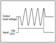
Zero Cross Circuit or Zero Cross Function
A circuit which starts operation with the AC load voltage at close to zero-phase.

The zero cross function turns ON the SSR when the AC load voltage is close to 0 V, thereby suppressing the noise generated by the load current when the load current rises quickly.
The generated noise will be partly imposed on the power line and the rest will be released in the air. The zero cross function effectively suppresses both noise paths.

A circuit that consists of a resistor R and capacitor C , and is used to prevent faulty ignition of an SSR triac by suppressing a sudden rise in the voltage applied to the triac.
Input
The voltage that serves as the standard value for an input signal voltage.
Operating voltage
The permissible voltage range within which an input signal voltage may fluctuate.
Must Operate Voltage
The minimum input voltage when the output status changes from OFF to ON.
Must Release Voltage
The maximum input voltage when the output status changes from ON to OFF.
The current that flows through the SSR when the rated voltage is applied.
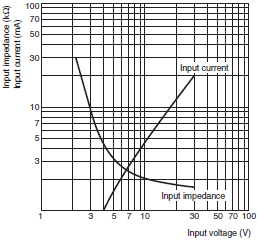
Input impedance
The impedance of the input circuit and the resistance of current-limiting resistors used.
In SSRs, which have a wide range of input voltages, the input impedance varies with the input voltage, and that causes the input current to change.
Applicable Input Impedance (Typical Examples)
G3F and G3H (without Indicators)

Output
The effective power supply voltage at which the load can be switched and the SSR can be continuously used when the SSR is OFF.
The effective value of the maximum current that can continuously flow into the output terminals under specified cooling conditions (such as the size, materials, and thickness of the heat sink, and the ambient temperature radiating conditions).
The effective value of the current that flows across the output terminals when a specified load voltage is applied to the SSR with output turned OFF.

Output ON voltage drop
The effective value of the AC voltage across the output terminals when the maximum load current flows through the SSR under specified cooling conditions (such as the size, materials, and thickness of heat sink, and the ambient temperature radiation conditions).
The minimum load current at which the SSR can operate normally.
Characteristics
Operate time
A time lag between the moment a specified signal voltage is applied to the input terminals and the output is turned ON.
A time lag between the moment the applied signal voltage is turned OFF and the output is turned OFF.
Insulation resistance
The resistance between the input and output terminals or between the I/O terminals and metal housing (heat sink) when a DC voltage is applied.
Dielectric strength
The effective AC voltage that the SSR can withstand when it is applied between the input terminals and output terminals or between the I/O terminals and metal housing (heat sink) for more than 1 minute.
Ambient operating temperature and humidity
The ranges of temperature and humidity in which the SSR can operate normally under specified cooling, input/output voltage, and current conditions.
The temperature range in which the SSR can be stored without voltage imposition.
Others
The maximum non-repeat current (approx. 1 or 2 repetitions per day) that can flow in the SSR. Expressed using the peak value at the commercial frequency in one cycle.
*This value was conventianally expressed as the "withstand inrush current",
but has been changed to "surge withstand current" because the former term was easily mistaken for inrush current of loads.
Counter-electromotive Force
A voltage that rises very steeply when the load is turned ON or OFF.
The resistance connected in parallel to the load in order to increase apparently small load currents, so that the ON/OFF of minute currents functions normally.


