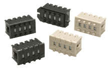
Thumbwheel Switches
| Introduction | Features |
| Principles | Classifications |
| Engineering Data |
|
|
|
Troubleshooting |
What Is a Thumbwheel Switch?
A Thumbwheel Switch is a setting switch that converts the numeric value selected by turning a disk-shaped part on which numbers are written into a binary, decimal, hexadecimal, or other code using the combination of ON and OFF signals for multiple contact circuits and that outputs the resulting code.

Features
Thumbwheel switches easily convert values to binary, decimal, or hexadecimal codes.
| Visually checking initial values | The selected value is displayed as is, so you can always check the set value visually. This makes it easier to prevent incorrect operation. |
| Maintaining set values | Conversion to a code uses only a mechanical mechanism, so the set value is maintained whether the power is ON or OFF. |
| Easy digital conversion | Conversion to a code is easy, which makes circuits and wiring simple and improves control system reliability and maintainability. |
Types
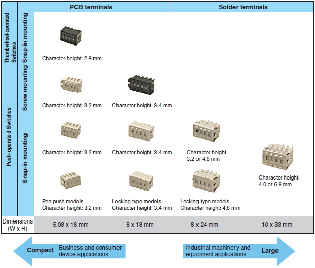
OMRON’s Thumbwheel Switch lineup is based on dimensions to match the scale of the device or equipment the Thumbwheel Switches is mounted in. Thumbwheel Switches are also divided by mounting method into screw-fastened and snap-in switches.
There are also Thumbwheel Switches that have a lock function that locks the set values and prevents them from being changed, as well as Thumbwheel Switches that can only be operated with a pen tip or other thin object.
First, select the external size that matches the device or equipment the Switch will be mounted in.

Structure
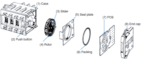
Our typical Thumbwheel Switch consists of a case, push buttons, slider, rotor, seal plate, packing, PCB, end caps, and other parts.

| (1) | Case | The case holds the components. The case sides have a mechanism for connecting Switches together in a single operation. |
| (2) | Push button | There is a plus push button for normal rotation and a minus push button for reverse rotation to set the value. Each push button has a mechanism to provide a click and to smoothly turn the rotor one step each time the push button is pressed. |
| (3) | Slider | The slider is fastened to the rotor. As the rotor turns, the tip of the slider slides on the PCB. The slider works as a moving contact that turns switch circuits ON and OFF by contacting different parts of the conductive pattern printed on the PCB. Gold alloy is used on the slider tip, which makes contact with the PCB, in order to enhance the contact reliability. |
| (4) | Rotor | The rotor is a disk-shaped part with numbers written on its circumferential surface. Turning the rotor sets the value of the Switch. |
| (5) | Seal plate | The seal plate is a transparent plastic part that keeps out foreign substances. It is also the cover for the display window. |
| (6) | Packing | The packing is made of elastic rubber. It is sandwiched between the PCB and the seal plate and keeps foreign substances out where the PCB makes contact with the slider. |
| (7) | PCB | The conductive pattern is plated with highly corrosion-resistant gold and maintains high contact reliability with the slider. A pattern with one circuit for each rotation angle is formed in order to convert the switch position into a numeric code. |
| (8) | End caps | End Caps are mounted on the Switch Units at each end. The Switch is installed by just pushing the mechanism on the End Caps into the corresponding hole. |


