Question
There is no response to commands sent from the host computer to the Meter via serial communications. What should I do?
Answer
Items to Check
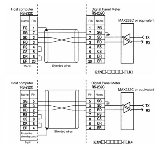
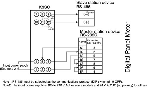
1.Refer to the following diagrams and check the wiring.
RS-232C
The RS-232C connection configuration is 1:1.
The maximum cable length is 15 m. To communicate over longer distances, use OMRON Z3RN RS-232C Optical Interfaces or K3SC Interface Converters (use 2 Units).
Use cable with shielded, twisted-pair wires (28 AWG or thicker).

RS-422
The RS-422 connection configuration is 1:1 or 1:N (when using K3SC Interface Converters).
With the 1:N configuration, up to 32 devices can be connected, including the host computer.
The maximum total cable length is 500 m.
Use cable with shielded, twisted-pair wires (28 AWG or thicker).

RS-485
The RS-422 connection configuration is 1:1 or 1:N. With the 1:N configuration, up to 32 devices can be connected, including the host computer.
The maximum total cable length is 500 m.
Use cable with shielded, twisted-pair wires (28 AWG or thicker).

2.Verify that the commands are being sent in ASCII, according to the communications format. Refer to the following diagrams for details.
3.Verify that the unit number, baud rate, data bits, stop bits, and parity settings are the same in the host computer and Digital Panel Meter.
For details, refer to the following figures.
Note:

CompoWay/F Communications
If an "H" is added after a number, like (02H) below, the number is expressed in hexadecimal. If the number is shown as a character string in double quotation marks, like "00" below, the number is expressed in ASCII characters.
Command Frame

Response Frame

Note:There will be no data if a command frame error occurs (end code other than "00" or "0F").
| STX | This code indicates the start of the communications frame (text). Always set (02H) in these characters in the first byte. This is a classifying number used to designate the start of a transmission. |
| Node number | Specifies the K3N[] Digital Panel Indicator Meter's unit number. When sending a broadcast transmission, specify "XX". No responses will be returned for a broadcast transmission. |
| Subaddress | Not used in the K3N[]. Always set to "00". |
| SID (Service ID) | Not used in the K3N[]. Always set to "0". |
| End code | Indicates the results of the command frame's execution. |
| Command text | This is the command itself. |
| MRC and SRC (command code) | Indicates the service to be used. |
| MRES and SRES (response code) | Indicates the results of communications. |
| ETX | This code indicates the end of the text. |
| BCC | This is the block check character. |
The BCC result is found by calculating the exclusive OR of the bytes from the node number through ETX.
BCC calculation method: The BCC is the result of an exclusive OR of all bytes from just after STX through ETX.
Specialized Communications Protocol
Communications Control Protocol
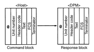
In the Digital Panel Meter Series, Host Link communications are the conversational type of communications protocol conforming to the PC's host link protocol. The host computer has the transmission right first, and initiates the communications. The transmission right is transferred with each block that is sent. When a command block is sent, a response block is always returned.

Note:
1.The unit number is equivalent to the unit number in the Programmable Controller.
2.When two or more devices are connected, do not duplicate the unit numbers.
Block Formats
The blocks sent from the host computer are called command blocks.
The blocks sent from the Digital Panel Meter are called response blocks.
A block begins with the start character (@) and communications address, and ends with the FCS code and terminator.

Applicable models: K3NX, K3NV, K3NR, K3NP, K3NH, and K3NC Digital Panel Indicators


