Question
What is the difference between the binary and BCD forms of math instructions?
Answer
The Internal Code of Math Instructions
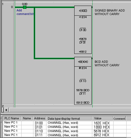
When using CX-Programmer FA Integrated Tool Package, as shown in the ladder program in Figure 1, both BINARY ADD instructions and BCD ADD instructions can be input and displayed in decimal form. The data conversion function of CX-Programmer makes this possible. You can see by looking at the internal code in the Watch Window in Figure 1 or the numeral data in Figure 2, that the internal code processed by the CPU Unit is actually binary.

Programming: CS1/CJ1-series Programmable Controller
Figure1. Ladder Program and Watch Window

Figure2. DM Area Monitor Display for Programmable Controller Memory (Binary Mode)
The BINARY ADD instructions can handle a range of values 3.27 times that of the BCD ADD instructions.
Choosing an Instruction: Checkpoint 1
As previously described, the internal code for the instructions is either binary or BCD format. The value ranges for the instructions are shown in Table 1.
| Mnemonic | Instruction name | Data type | Value range |
| + | SIGNED BINARY ADD WITH CARRY | INT | -32768 to 32767 |
| +B | BCD ADD WITHOUT CARRY | UNIT_BCD | 0 to 9999 |
Table 1
As shown in Table 1, the difference between the "+" instruction and the +B instruction is whether the values are signed or unsigned. It can also be seen that the "+" instruction can handle a range of values 3.27 times that of the +B instruction even when the value range is limited to positive numbers. This difference in the range of values that can be handled is an important factor when selecting math instructions.
Considering the I/O Values of Programmable Controllers
Choosing an Instruction: Checkpoint 2
Should binary or BCD format be selected? One more important point to be considered when selecting the instruction is the form of the numeric inputs for the math instruction. Table 2 shows a list of common I/O signals used by Programmable Controllers and the main code (BCD or binary) that would be used for math processing.
| Item | BCD | BIN | |
| Input | Thumbwheel switches | Yes | |
| Ten-key switches | Yes | ||
| Parallel transfer data | Yes | Yes | |
| Serial communications data (ASCll) | Yes | Yes | |
| A/D conversion data | Yes | ||
| Output | Digital display units | Yes | |
| Printers (ASCll) | Yes | ||
| Parallel transfer data | Yes | Yes | |
| Serial communications data (ASCll) | Yes | Yes | |
| D/A conversion data | Yes |
Table2. I/O Signals for Programmable Controllers
Case Study of Selecting Math Instructions (Overview)
To summarize the above, the two checkpoints for math instruction selection are as follows:
1.The difference in range of values handled by binary instructions and BCD instructions
2.I/O format for math formulas
Here we will give some examples of how to decide math instructions using checkpoints 1 and 2.
Example 1: Relatively Simple Calculation
Use BINARY ADD
An internal offset value is added to a 4-digit BCD input value from a thumbwheel switch, and the result is output as a 4-digit BCD value to a digital display unit.
Use BINARY DIVIDE
A 12-bit binary value from an A/D conversion unit is divided by an internal variable, and a 12-bit binary value is output to a D/A conversion unit after scaling.
Example 2: Comparatively Complex Calculation with Multiple Input Parameters
When there are multiple input parameters, depending on the input device and communications control specifications, BCD data and binary data may both exist. When this occurs consider the following two questions as a general guide to select the math instruction:
1.What is the form of the output value?
2.What is the value range during calculation processing?
After the instruction has been decided, other data in other forms will be converted into binary or BCD using the binary or BCD conversation instructions.
Recommended Products
Other Programmable Controllers FAQ
-
 What products are recommended as substitutes for the C200H-CPU01 Programmable Controller?
-
 How can I connect a C200H Programmable Controller's CPU Unit with an IBM PC/AT or compatible computer?
-
 Why communication error occurs during CX-Programmer FA Integrated Tool Package get online with Programmable Controller?


