| Function |
Description |
| Communications |
Cyclic
communications |
I/O data (process data) in the IO-Link devices is cyclically shared with the IO-Link Master Unit as the IO-Link communications master.
At the same time, this data and the status of the IO-Link Master Unit is cyclically shared with the host communications master, with the IO-Link Master Unit operating as a slave of the controller.
Cyclic communications can be used to check the amount of detection performance deterioration in devices, and to check changes in usage conditions, such as the amount of incident light for photoelectric sensors, stability detection margins, and excessive proximity for proximity sensors. |
Message
communications |
The controller can send messages (commands) to the IO-Link Master Unit and receive the response from the IO-Link Master Unit.
The IO-Link Master Unit can also function as a gateway to send messages (commands and responses) between the controller and the IO-Link devices.
During operation, you can change and adjust device parameters, such as threshold settings, tuning execution, and ON-delay time changes, from a program.
Or, during operation, you can check the internal status, such as the operating times of devices. |
| Communications mode settings |
You can select any of the following modes for each port:
IO-Link Mode, SIO (DI) Mode, SIO (DO) Mode, or Disable Port
This allows you to combine IO-Link communications and digital I/O in a single terminal or unit. |
| Digital inputs for pin 2 |
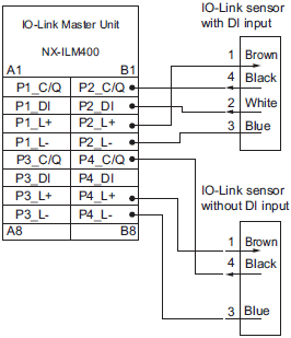
In IO-Link Mode, you can perform digital input with pin 2 while performing IO-Link communications. |
Automatic baud rate setting for
IO-Link communications |
The IO-Link Master Unit automatically matches the specific baud rates (COM1, COM2, or COM3) of the IO-Link devices to communicate with the IO-Link devices.
Therefore, it is not necessary to set the baud rate of the connected device for each port. |
| Connected device verification |
This function is used to verify the configuration of IO-Link devices that are connected to the IO-Link Master Unit against the registered IO-Link device configuration settings when the power supply is turned ON.
The user can enable or disable connected device verification. |
IO-Link communications error
detection |
This function detects IO-Link cable breaks, disconnections from IO-Link device ports, error-level device events, device configuration verification errors, and IO-Link device malfunctions. |
Detection of short-circuits in I/O
cables |
This function detects short-circuits in I/O cables |
| Notification of input data validity |
The controller can use the Input Data Enabled Flags to determine whether input data * is valid. |
Load rejection for controller
communications error |
This function turns OFF outputs from the IO-Link Master Unit when an error occurs in communications with the controller in IO-Link Mode or in an SIO mode.
This prevents output operations with incorrect values from host communications. |
Reading IO-Link total
communications retries |
The IO-Link total communications retries can be read from the CX-ConfiguratorFDT.
You can use this function to determine communications status as affected by I/O communications noise or other factors. |
| Digital input filter |
You can set a filter processing time interval for digital inputs in SIO (DI) Mode or for digital inputs for pin 2 in IO-Link Mode.
This lets you eliminate data corruption that can result from noise or switch chattering.
This function can also be used to implement an ON delay and an OFF delay. |
Backup and restoration of
parameter settings in IO-Link
devices |
This function is used to back up parameter settings in IO-Link devices in the IO-Link Master Unit or restore them to IO-Link devices.
This eliminates the need to set parameters again after replacing an IO-Link device. |
| Event log |
The event log records events (including errors) that occur in the IO-Link Master Unit and the IO-Link devices.
This enables partial troubleshooting for NJ/NX-series Controllers and NY-series Industrial PCs. |


