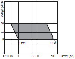
Page top

Building Automation


Industrial Automation


Power Automation & Safety

Bangladesh Distributor

WL, WLM

Two-circuit Limit Switch/Long-life Two-circuit Limit Switch

WL, WLM

Wide Range of Two-circuit Switches; Select One for the Operating Environment/Application

General-purpose/Weather-proof Switches

Ratings

Standard-load Switches

Item Rated
voltage
(V)
Non-inductive load (A) Inductive load (A)
Resistive load Lamp load Inductive load Motor load
NC NO NC NO NC NO NC NO
Basic models, overtravel
models (except for high-
sensitivity models), and
high-precision models
125 VAC
250 VAC
500 VAC
10
10
10
3
2
1.5
1.5
1
0.8
10
10
3
5
3
1.5
2.5
1.5
0.8
8 VDC
14 VDC
30 VDC
125 VDC
250 VDC
10
10
6
0.8
0.4
6
6
4
0.2
0.1
3
3
3
0.2
0.1
10
10
6
0.8
0.4
6
6
4
0.2
0.1
High-sensitivity
overtravel models
125 VAC
250 VAC
5
5
--- --- ---
125 VDC
250 VDC
0.4
0.2
--- --- ---

Note: 1. The above figures are for steady-state currents.
          2. Inductive loads have a power factor of 0.4 min. (AC) and a time constant of 7 ms max. (DC).
          3. A lamp load has an inrush current of 10 times the steady-state current.
          4. A motor load has an inrush current of 6 times the steady-state current.
          5. For PC loads, use the microload models.

Inrush current NC 30 A max. (15 A max. *)
NO 20 A max. (10 A max. *)

* For high-sensitivity overtravel models.

Minimum applicable load 5 VDC 160 mA

Microload Switches

(Refer to these ratings before using the product.)

Rated voltage (V) Rated current (A) - Resistive load
AC 125 0.1
DC 30

Operation in the following ranges will produce optimum performance.

Recommended load range 5 to 30 VDC
0.5 to 100 mA

WL, WLM Specifications 12

Recommended load range 5 VDC 1 mA

Characteristics

Degree of protection IP67
Durability
*1
Mechanical 15,000,000 operations min. *2
Electrical 750,000 operations min. *3
Operating speed 1 mm/s to 1 m/s (in case of WLCA2)
Operating
frequency
Mechanical 120 operations/minute min.
Electrical 30 operations/minute min.
Rated frequency 50/60 Hz
Insulation resistance 100 MΩ min. (at 500 VDC)
Contact resistance 25 mΩ max. (initial value for the built-in switch when tested alone) *6
Dielectric
strength
Between terminals of the
same polarity
1,000 VAC (600 VAC), 50/60 Hz for 1 min
Between current-carrying
metal part and ground
2,200 VAC (1,500 VAC), 50/60 Hz for 1 min/Uimp 2.5 kV
Between each terminal and
non-current-carrying metal
part
2,200 VAC (1,500 VAC), 50/60 Hz for 1 min/Uimp 2.5 kV
Rated insulation voltage (Ui) 250 V (EN60947-5-1)
Pollution degree (operating environment) 3 (EN60947-5-1)
Short-circuit protective device (SCPD) 10 A, fuse type gG or gI (IEC60269)
Conditional short-circuit current 100 A (EN60947-5-1)
Conventional enclosed thermal current
(Ithe)
10 A, 0.5 A (EN60947-5-1)
Protection against electric shock Class I
Vibration
resistance
Malfunction 10 to 55 Hz, 1.5-mm double amplitude *4
Shock
resistance
Destruction 1,000 m/s2 max.
Malfunction 300 m/s2 max. *4
Ambient operating temperature -10°C to +80°C (with no icing) *5
Ambient operating humidity 35% to 95% RH
Weight Approx. 275 g (in case of WLCA2)

Note: 1. The above figures are initial values.
           2. The figures in parentheses for dielectric strength are those for the highsensitivity overtravel models.
*1. The values are calculated at an operating temperature of +5°C to +35°C and an operating humidity of 40% to
       70%RH. Contact your OMRON sales representative for more detailed information on other operating environments.
*2. Durability is 10,000,000 operations min. for general-purpose or high-sensitivity overtravel models, and for flexible
       rod models.
       500,000 operations min. for weather-proof models.
*3. Durability is 500,000 operations min. for high-sensitivity models. All microload models are 1,000,000 operations min.
       500,000 operations min. for weather-proof models.
*4. Except flexible rod models. The shock resistance (malfunction) for microload models is 200 m/s2 max.
*5. For low-temperature models this is –40°C to +40°C (with no icing). For heatresistant models the range is +5°C to
       +120°C.
*6. For microload models, the contact resistance is 50 mΩ max. (initial value for built-in switch).

Spatter-prevention Switches

Ratings

Screw terminals

Item Rated
voltage
(V)
Non-inductive load (A) Inductive load (A)
Resistive load Lamp load Inductive load Motor load
NC NO NC NO NC NO NC NO
WL[]-LES 125 VAC
250 VAC
10
10
3
2
1.5
1
10
10
5
5
2.5
1.5
WL[]-LDS 115 VAC 10 3 1.5 10 5 2.5
12 VDC
24 VDC
48 VDC
10
6
3
6
4
2
3
3
1.5
10
6
3
6
4
2

Note: 1. The above figures are for steady-state currents.
          2. Inductive loads have a power factor of 0.4 min. (AC) and a time constant of 7 ms max. (DC).
          3. A lamp load has an inrush current of 10 times the steady-state current.
          4. A motor load has an inrush current of 6 times the steady-state current.

Inrush current NC 30 A max.
NO 20 A max.
Operating temperature -10°C to +80°C (with no icing)
Operating humidity 35% to 95%RH max.

Characteristics

Degree of protection IP67
Durability
*1
Mechanical 15,000,000 operations min. *2
Electrical 750,000 operations min. *3
Operating speed 1 mm/s to 1 m/s (in case of WLCA2)
Operating
frequency
Mechanical 120 operations/minute min.
Electrical 30 operations/minute min.
Rated frequency 50/60 Hz
Insulation resistance 100 MΩ min. (at 500 VDC)
Contact resistance 25 mΩ max. (initial value for the builtin switch when tested alone)
Dielectric
strength
Between terminals of the same
polarity
1,000 VAC (600 VAC), 50/60 Hz for 1 min
Between current-carrying
metal part and ground
2,200 VAC (1,500 VAC), 50/60 Hz for 1 min/Uimp 2.5 kV
Between each terminal and non-
current-carrying metal part
2,200 VAC (1,500 VAC), 50/60 Hz for 1 min/Uimp 2.5 kV
Rated insulation voltage (Ui) 250 V (EN60947-5-1)
Pollution degree (operating environment) 3 (EN60947-5-1)
Short-circuit protective device (SCPD) 10 A, fuse type gG or gI (IEC60269)
Conditional short-circuit current 100 A (EN60947-5-1)
Conventional enclosed thermal current
(Ithe)
10 A, 0.5 A (EN60947-5-1)
Protection against electric shock Class I
Vibration
resistance
Malfunction 10 to 55 Hz, 1.5-mm double amplitude
Shock
resistance
Destruction 1,000 m/s2 max.
Malfunction 300 m/s2 max.
Ambient operating temperature -10°C to +80°C (with no icing)
Ambient operating humidity 35% to 95%RH
Weight Approx. 275 g (in case of WLCA2)

Note: 1. The above figures are initial values.
          2. The figures in parentheses for dielectric strength are those for the highsensitivity overtravel models.
*1. The values are calculated at an operating temperature of +5°C to +35°C and an operating humidity of 40% to
       70%RH. Contact your OMRON sales representative for more detailed information on other operating environments.
*2. Durability is 10,000,000 operations min. for general-purpose or high-sensitivity overtravel models.
*3. Durability is 500,000 operations min. for high-precision models. All microload models however, are 1,000,000
       operations min.

Long-life Switches

Ratings

General Ratings (Refer to these ratings before using the product.)

Screw Terminal Switches

Item Rated
voltage
(V)
Non-inductive load (A) Inductive load (A)
Resistive load Lamp load Inductive load Motor load
NC NO NC NO NC NO NC NO
Basic models, overtravel
models, (except for high-
sensitivity models), and
high-precision models
115 AC 10 3 1.5 10 5 2.5
12 DC
24 DC
48 DC
115 DC
10
6
3
0.8
6
4
2
0.2
3
3
1.5
0.2
10
6
3
0.8
6
4
2
0.2
High-sensitivity overtravel
models
115 AC 5 --- --- ---
115 DC 0.4 --- --- ---

Inrush current NC 30 A max. (15 A max. *)
NO 20 A max. (10 A max. *)

* For high-sensitivity overtravel models.

Direct-wired Connector and Pre-wired Connector Switches

Model Rated
voltage
(V)
Non-inductive load (A) Inductive load (A)
Resistive load Lamp load Inductive load Motor load
NC NO NC NO NC NO NC NO
DC 12 DC 3 3 3 3 3 3 3 3
24 DC 3 3 3 3 3 3 3 3
48 DC 3 3 3 3 3 3 3 3
115 DC 0.8 0.8 0.2 0.2 0.8 0.8 0.2 0.2
AC 115 AC 3 3 3 1.5 3 3 3 2.5

Note: 1. The above figures are for steady-state currents.
          2. Inductive loads have a power factor of 0.4 min. (AC) and a time constant of 7 ms max. (DC).
          3. A lamp load has an inrush current of 10 times the steady-state current.
          4. A motor load has an inrush current of 6 times the steady-state current.

Characteristics

Degree of protection IP67
Durability
*
Mechanical 30,000,000 operations min.
Electrical 30,000,000 operations min. (10 mA at 24 VDC, resistive load)
750,000 operations min. (10 A at 115 VAC, resistive load), but for high-
precision models: 500,000 operations min. (10 A at 115 VAC, resistive load)
Operating speed 1 mm/s to 1 m/s (in case of WLCA2)
Operating
frequency
Mechanical 120 operations/minute
Electrical 30 operations/minute
Rated frequency 50/60 Hz
Insulation resistance 100 MΩ min. (at 500 VDC)
Contact resistance 25 mΩ max. (initial value for the builtin switch when tested alone)
Dielectric
strength
(50/60 Hz
for 1 min)
Between terminals of the
same polarity
1,000 VAC (except connector models)
Between current-carrying
metal part and ground
2,200 VAC (1,500 V)
Between each terminal
and non-current-
carrying metal part
2,200 VAC (1,500 V)
Vibration
resistance
Malfunction 10 to 55 Hz, 1.5-mm double amplitude
Shock
resistance
Destruction 1,000 m/s2 max.
Malfunction 300 m/s2 max.
Ambient operating temperature -10°C to +80°C (with no icing)
Ambient operating humidity 35% to 95%RH
Weight Approx. 275 g (in case of WLCA2)

Note: The figures in parentheses for dielectric strength, are those for overtravel (high-sensitivity) or connector models.
* The values are calculated at an operating temperature of +5°C to +35°C, and an operating humidity of 40% to
    70%RH. Contact your OMRON sales representative for more detailed information on other operating environments.