Page top

Building Automation


Industrial Automation


Power Automation & Safety

Bangladesh Distributor

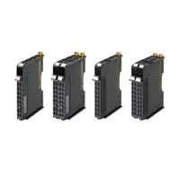
NX-TS

NX-series Temperature Input Unit

NX-TS

Temperature Input Units for Standard and High-speed, High-precision Temperature measurement and control

about this Product Family

General Specification

Item Specification
Enclosure Mounted in a panel
Grounding method Ground to 100 Ω or less
Operating
environment
Ambient operating
temperature
0 to 55°C
Ambient operating
humidity
10% to 95% (with no condensation or icing)
Atmosphere Must be free from corrosive gases.
Ambient storage
temperature
-25 to 70°C (with no condensation or icing)
Altitude 2,000 m max.
Pollution degree 2 or less: Conforms to JIS B3502 and IEC 61131-2.
Noise immunity 2 kV on power supply line (Conforms to IEC61000-4-4.)
Overvoltage category Category II: Conforms to JIS B3502 and IEC 61131-2.
EMC immunity level Zone B
Vibration resistance Conforms to IEC 60068-2-6.
5 to 8.4 Hz with 3.5-mm amplitude, 8.4 to 150 Hz, acceleration of 9.8 m/s2,
100 min each in X, Y, and Z directions
(10 sweeps of 10 min each = 100 min total)
Shock resistance Conforms to IEC 60068-2-27. 147 m/s2, 3 times each in X, Y, and Z directions
Applicable standards * cULus: Listed (UL508), ANSI/ISA 12.12.01, EU: EN 61131-2, C-Tick or RCM,
KC Registration, NK, LR

* Ask your OMRON representative for the most recent applicable standards for each model.

Temperature Input Unit Specifications

Temperature Input Unit (Thermocouple Input type) 2 points NX-TS2101

Unit name Temperature Input Unit
(thermocouple input type)
Model NX-TS2101
Number of points 2 points External connection
terminals
Screwless clamping terminal block (16
terminals)
I/O refreshing
method
Free-Run refreshing
Indicator TS indicator
3189_sp_2_1
Temperature sensor K, J, T, E, L, U, N, R, S, B, WRe5-26,
PLII
Input conversion range ±20°C of the input range
Absolute maximum
rating
±130 mV
Input impedance 20 kΩ min.
Resolution 0.1°C max. *1
Reference accuracy *2
Temperature
coefficient
*2
Cold junction
compensation error
±1.2°C *3 *4
Input disconnection
detection current
Approx. 0.1 μA
Warm-up period 30 minutes Conversion time 250 ms/Unit
Dimensions 12 (W) x 100 (H) x 71 (D) Isolation method Between the input and the NX bus:
Power = Transformer, Signal =
Photocoupler
Between inputs: Power = Transformer,
Signal = Photocoupler
Insulation
resistance
20 MΩ min. between isolated
circuits (at 100 VDC)
Dielectric strength 510 VAC between isolated circuits for
1 minute at a leakage current of 5 mA
max.
I/O power supply
method
No supply Current capacity of
I/O power supply
terminal
Without I/O power supply terminals
NX Unit power
consumption
• Connected to a CPU Unit
1.25 W max.
• Connected to a Communi-
cations Coupler Unit
0.90 W max.
Current consumption
from I/O power supply
No consumption
Weight 70 g max.
Installation
orientation and
restrictions
Installation orientation:
• Connected to a CPU Unit: Possible in upright installation.
• Connected to a Communications Coupler Unit: Possible in 6 orientations.
Restrictions:
The cold junction compensation error is restricted according to the installation orientation and the
power consumption of adjacent Units. Refer to Cold Junction Compensation Error Specifications for
Units That Take a Thermocouple Input Type.
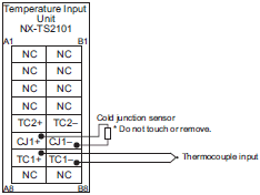
Terminal
connection
diagram
3189_sp_2_2

*1. The resolution is 0.2°C max. when the input type is R, S, or W.
*2. Refer to Reference Accuracy and Temperature Coefficient According to the Input Type and Measurement
       Temperature.
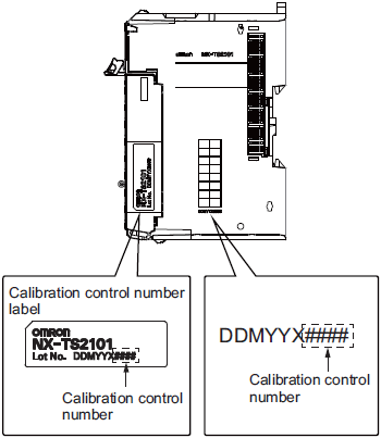
*3. The overall accuracy is guaranteed for a set consisting of a cold junction sensor that is mounted on the terminal
       block and a Temperature Input Unit. Be sure to use the terminal block and the Temperature Input Unit together.
       A calibration control number is both displayed on the terminal block and the Unit. Make sure to return the terminal
       block (including a cold junction sensor mounted) and the Unit together for repair.
*4. Refer to Cold Junction Compensation Error Specifications for Units That Take a Thermocouple Input Type for the
       specifications for each set of operating conditions.

Temperature Input Unit (Thermocouple Input type) 2 points NX-TS2102

Unit name Temperature Input Unit
(thermocouple input type)
Model NX-TS2102
Number of points 2 points External connection
terminals
Screwless clamping terminal block (16
terminals)
I/O refreshing
method
Free-Run refreshing
Indicator TS indicator
3189_sp_3_1
Temperature sensor K, J, T, E, L, U, N, R, S, WRe5-26, PLII
Input conversion range ±20°C of the input range
Absolute maximum
rating
±130 mV
Input impedance 20 kΩ min.
Resolution 0.01°C max.
Reference accuracy *1
Temperature
coefficient
*1
Cold junction
compensation error
±1.2°C *2 *3
Input disconnection
detection current
Approx. 0.1 μA
Warm-up period 45 minutes Conversion time 10 ms/Unit
Dimensions 12 (W) x 100 (H) x 71 (D) Isolation method Between the input and the NX bus:
Power = Transformer, Signal = Digital
isolator
Between inputs: Power = Transformer,
Signal = Digital isolator
Insulation
resistance
20 MΩ min. between isolated
circuits (at 100 VDC)
Dielectric strength 510 VAC between isolated circuits for
1 minute at a leakage current of 5 mA
max.
I/O power supply
method
No supply Current capacity of
I/O power supply
terminal
Without I/O power supply terminals
NX Unit power
consumption
• Connected to a CPU Unit
1.15 W max.
• Connected to a Communi-
cations Coupler Unit
0.80 W max.
Current consumption
from I/O power supply
No consumption
Weight 70 g max.
Installation
orientation and
restrictions
Installation orientation:
• Connected to a CPU Unit: Possible in upright installation.
• Connected to a Communications Coupler Unit: Possible in 6 orientations.
Restrictions:
The cold junction compensation error is restricted according to the installation orientation and the
power consumption of adjacent Units. Refer to Cold Junction Compensation Error Specifications for
Units That Take a Thermocouple Input Type.
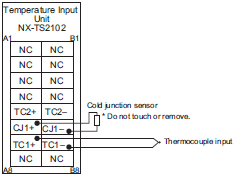
Terminal
connection
diagram
3189_sp_3_2

*1. Refer to Reference Accuracy and Temperature Coefficient According to the Input Type and Measurement
       Temperature.
*2. The overall accuracy is guaranteed for a set consisting of a cold junction sensor that is mounted on the terminal
       block and a Temperature Input Unit. Be sure to use the terminal block and the Temperature Input Unit together.
       A calibration control number is both displayed on the terminal block and the Unit. Make sure to return the terminal
       block (including a cold junction sensor mounted) and the Unit together for repair.
*3. Refer to Cold Junction Compensation Error Specifications for Units That Take a Thermocouple Input Type for the
       specifications for each set of operating conditions.

Temperature Input Unit (Thermocouple Input type) 2 points NX-TS2104

Unit name Temperature Input Unit
(thermocouple input type)
Model NX-TS2104
Number of points 2 points External connection
terminals
Screwless clamping terminal block (16
terminals)
I/O refreshing
method
Free-Run refreshing
Indicator TS indicator
3189_sp_4_1
Temperature sensor K, J, T, E, L, U, N, R, S, WRe5-26, PLII
Input conversion range ±20°C of the input range
Absolute maximum
rating
±130 mV
Input impedance 20 kΩ min.
Resolution 0.001°C max.
Reference accuracy *1
Temperature
coefficient
*1
Cold junction
compensation error
±1.2°C *2 *3
Input disconnection
detection current
Approx. 0.1 μA
Warm-up period 45 minutes Conversion time 60 ms/Unit
Dimensions 12 (W) x 100 (H) x 71 (D) Isolation method Between the input and the NX bus:
Power = Transformer, Signal = Digital
isolator
Between inputs: Power = Transformer,
Signal = Digital isolator
Insulation
resistance
20 MΩ min. between isolated
circuits (at 100 VDC)
Dielectric strength 510 VAC between isolated circuits for
1 minute at a leakage current of 5 mA
max.
I/O power supply
method
No supply Current capacity of
I/O power supply
terminal
Without I/O power supply terminals
NX Unit power
consumption
• Connected to a CPU Unit
0.95 W max.
• Connected to a Communi-
cations Coupler Unit
0.80 W max.
Current consumption
from I/O power supply
No consumption
Weight 70 g max.
Installation
orientation and
restrictions
Installation orientation:
• Connected to a CPU Unit: Possible in upright installation.
• Connected to a Communications Coupler Unit: Possible in 6 orientations.
Restrictions:
The cold junction compensation error is restricted according to the installation orientation and the
power consumption of adjacent Units. Refer to Cold Junction Compensation Error Specifications for
Units That Take a Thermocouple Input Type.
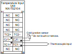
Terminal
connection
diagram
3189_sp_4_2

*1. Refer to Reference Accuracy and Temperature Coefficient According to the Input Type and Measurement
       Temperature.
*2. The overall accuracy is guaranteed for a set consisting of a cold junction sensor that is mounted on the terminal
       block and a Temperature Input Unit. Be sure to use the terminal block and the Temperature Input Unit together.
       A calibration control number is both displayed on the terminal block and the Unit. Make sure to return the terminal
       block (including a cold junction sensor mounted) and the Unit together for repair.
*3. Refer to Cold Junction Compensation Error Specifications for Units That Take a Thermocouple Input Type for the
       specifications for each set of operating conditions.

Temperature Input Unit (Resistance Thermometer Input type) 2 points NX-TS2201

Unit name Temperature Input Unit
(resistance thermometer
input type)
Model NX-TS2201
Number of points 2 points External connection
terminals
Screwless clamping terminal block (16
terminals)
I/O refreshing
method
Free-Run refreshing
Indicator TS indicator
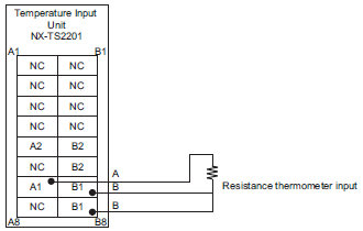
3189_sp_5_1
Temperature sensor Pt100 (three-wire)/Pt1000 (three-wire)
Input conversion range ±20°C of the input range
Input detection current Approx. 0.25 mA
Resolution 0.1°C max.
Reference accuracy *
Temperature
coefficient
*
Effect of conductor
resistance
0.06°C/Ω max. (also 20 Ω max.)
Warm-up period 10 minutes Conversion time 250 ms/Unit
Dimensions 12 (W) x 100 (H) x 71 (D) Isolation method Between the input and the NX bus:
Power = Transformer, Signal =
Photocoupler
Between inputs: Power = Transformer,
Signal = Photocoupler
Insulation
resistance
20 MΩ min. between isolated
circuits (at 100 VDC)
Dielectric strength 510 VAC between isolated circuits for
1 minute at a leakage current of 5 mA
max.
I/O power supply
method
No supply Current capacity of
I/O power supply
terminal
Without I/O power supply terminals
NX Unit power
consumption
• Connected to a CPU Unit
1.25 W max.
• Connected to a Communi-
cations Coupler Unit
0.90 W max.
Current consumption
from I/O power supply
No consumption
Weight 70 g max.
Installation
orientation
and restrictions
Installation orientation:
• Connected to a CPU Unit: Possible in upright installation.
• Connected to a Communications Coupler Unit: Possible in 6 orientations.
Restrictions: No restrictions
Terminal
connection
diagram
3189_sp_5_2

* Refer to Reference accuracy and temperature coefficient according to the input type and measurement temperature.

Temperature Input Unit (Resistance Thermometer Input type) 2 points NX-TS2202

Unit name Temperature Input Unit
(resistance thermometer
input type)
Model NX-TS2202
Number of points 2 points External connection
terminals
Screwless clamping terminal block (16
terminals)
I/O refreshing
method
Free-Run refreshing
Indicator TS indicator
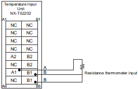
3189_sp_6_1
Temperature sensor Pt100 (three-wire)
Input conversion range ±20°C of the input range
Input detection current Approx. 0.25 mA
Resolution 0.01°C max.
Reference accuracy *
Temperature
coefficient
*
Effect of conductor
resistance
0.06°C/Ω max. (also 20 Ω max.)
Warm-up period 30 minutes Conversion time 10 ms/Unit
Dimensions 12 (W) x 100 (H) x 71 (D) Isolation method Between the input and the NX bus:
Power = Transformer, Signal = Digital
isolator
Between inputs: Power = Transformer,
Signal = Digital isolator
Insulation
resistance
20 MΩ min. between isolated
circuits (at 100 VDC)
Dielectric strength 510 VAC between isolated circuits for
1 minute at a leakage current of 5 mA
max.
I/O power supply
method
No supply Current capacity of
I/O power supply
terminal
Without I/O power supply terminals
NX Unit power
consumption
• Connected to a CPU Unit
1.15 W max.
• Connected to a Communi-
cations Coupler Unit
0.75 W max.
Current consumption
from I/O power supply
No consumption
Weight 70 g max.
Installation
orientation
and restrictions
Installation orientation:
• Connected to a CPU Unit: Possible in upright installation.
• Connected to a Communications Coupler Unit: Possible in 6 orientations.
Restrictions: No restrictions
Terminal
connection
diagram
3189_sp_6_2

* Refer to Reference accuracy and temperature coefficient according to the input type and measurement temperature.

Temperature Input Unit (Resistance Thermometer Input type) 2 points NX-TS2204

Unit name Temperature Input Unit
(resistance thermometer
input type)
Model NX-TS2204
Number of points 2 points External connection
terminals
Screwless clamping terminal block (16
terminals)
I/O refreshing
method
Free-Run refreshing
Indicator TS indicator
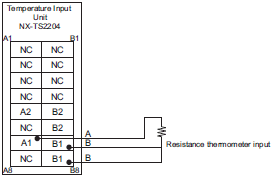
3189_sp_7_1
Temperature sensor Pt100 (three-wire)/Pt1000 (three-wire)
Input conversion range ±20°C of the input range
Input detection current Approx. 0.25 mA
Resolution 0.001°C max.
Reference accuracy *
Temperature
coefficient
*
Effect of conductor
resistance
0.06°C/Ω max. (also 20 Ω max.)
Warm-up period 30 minutes Conversion time 60 ms/Unit
Dimensions 12 (W) x 100 (H) x 71 (D) Isolation method Between the input and the NX bus:
Power = Transformer, Signal = Digital
isolator
Between inputs: Power = Transformer,
Signal = Digital isolator
Insulation
resistance
20 MΩ min. between isolated
circuits (at 100 VDC)
Dielectric strength 510 VAC between isolated circuits for
1 minute at a leakage current of 5 mA
max.
I/O power supply
method
No supply Current capacity of
I/O power supply
terminal
Without I/O power supply terminals
NX Unit power
consumption
• Connected to a CPU Unit
0.90 W max.
• Connected to a Communi-
cations Coupler Unit
0.75 W max.
Current consumption
from I/O power supply
No consumption
Weight 70 g max.
Installation
orientation
and restrictions
Installation orientation:
• Connected to a CPU Unit: Possible in upright installation.
• Connected to a Communications Coupler Unit: Possible in 6 orientations.
Restrictions: No restrictions
Terminal
connection
diagram
3189_sp_7_2

* Refer to Reference accuracy and temperature coefficient according to the input type and measurement temperature.

Temperature Input Unit (Thermocouple Input type) 2 points NX-TS3101

Unit name Temperature Input Unit
(thermocouple input type)
Model NX-TS3101
Number of points 4 points External connection
terminals
Screwless clamping terminal block
(16 terminals x 2)
I/O refreshing
method
Free-Run refreshing
Indicator TS indicator
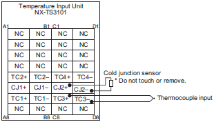
3189_sp_8_1
Temperature sensor K, J, T, E, L, U, N, R, S, B, WRe5-26,
PLII
Input conversion range ±20°C of the input range
Absolute maximum
rating
±130 mV
Input impedance 20 kΩ min.
Resolution 0.1°C max. *1
Reference accuracy *2
Temperature
coefficient
*2
Cold junction
compensation error
±1.2°C *3 *4
Input disconnection
detection current
Approx. 0.1μA
Warm-up period 30 minutes Conversion time 250 ms/Unit
Dimensions 24 (W) x 100 (H) x 71 (D) Isolation method Between the input and the NX bus:
Power = Transformer, Signal =
Photocoupler
Between inputs: Power = Transformer,
Signal = Photocoupler
Insulation
resistance
20 MΩ min. between isolated
circuits (at 100 VDC)
Dielectric strength 510 VAC between isolated circuits for
1 minute at a leakage current of 5 mA
max.
I/O power supply
method
No supply Current capacity of
I/O power supply
terminal
Without I/O power supply terminals
NX Unit power
consumption
• Connected to a CPU Unit
1.75 W max.
• Connected to a Communi-
cations Coupler Unit
1.30 W max.
Current consumption
from I/O power supply
No consumption
Weight 140 g max.
Installation
orientation and
restrictions
Installation orientation:
• Connected to a CPU Unit: Possible in upright installation.
• Connected to a Communications Coupler Unit: Possible in 6 orientations.
Restrictions:
The cold junction compensation error is restricted according to the installation orientation and the
power consumption of adjacent Units. Refer to Cold Junction Compensation Error Specifications for
Units That Take a Thermocouple Input Type.
Terminal
connection
diagram
3189_sp_8_2

*1. The resolution is 0.2°C max. when the input type is R, S, or W.
*2. Refer to Reference Accuracy and Temperature Coefficient According to the Input Type and Measurement
       Temperature.
*3. The overall accuracy is guaranteed for a set consisting of a cold junction sensor that is mounted on the terminal
       block and a Temperature Input Unit. Be sure to use the terminal block and the Temperature Input Unit together.
       A calibration control number is both displayed on the terminal block and the Unit. Make sure to return the terminal
       block (including a cold junction sensor mounted) and the Unit together for repair.
*4. Refer to Cold Junction Compensation Error Specifications for Units That Take a Thermocouple Input Type for the
       specifications for each set of operating conditions.

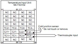
Temperature Input Unit (Thermocouple Input type) 4 points NX-TS3102

Unit name Temperature Input Unit
(thermocouple input type)
Model NX-TS3102
Number of points 4 points External connection
terminals
Screwless clamping terminal block
(16 terminals x 2)
I/O refreshing
method
Free-Run refreshing
Indicator TS indicator
3189_sp_9_1
Temperature sensor K, J, T, E, L, U, N, R, S, WRe5-26, PLII
Input conversion range ±20°C of the input range
Absolute maximum
rating
±130 mV
Input impedance 20 kΩ min.
Resolution 0.01°C max.
Reference accuracy *1
Temperature
coefficient
*1
Cold junction
compensation error
±1.2°C *2 *3
Input disconnection
detection current
Approx. 0.1 μA
Warm-up period 45 minutes Conversion time 10 ms/Unit
Dimensions 24 (W) x 100 (H) x 71 (D) Isolation method Between the input and the NX bus:
Power = Transformer, Signal = Digital
isolator
Between inputs: Power = Transformer,
Signal = Digital isolator
Insulation
resistance
20 MΩ min. between isolated
circuits (at 100 VDC)
Dielectric strength 510 VAC between isolated circuits for
1 minute at a leakage current of 5 mA
max.
I/O power supply
method
No supply Current capacity of
I/O power supply
terminal
Without I/O power supply terminals
NX Unit power
consumption
• Connected to a CPU Unit
1.55 W max.
• Connected to a Communi-
cations Coupler Unit
1.10 W max.
Current consumption
from I/O power supply
No consumption
Weight 140 g max.
Installation
orientation and
restrictions
Installation orientation:
• Connected to a CPU Unit: Possible in upright installation.
• Connected to a Communications Coupler Unit: Possible in 6 orientations.
Restrictions:
The cold junction compensation error is restricted according to the installation orientation and the
power consumption of adjacent Units. Refer to Cold Junction Compensation Error Specifications for
Units That Take a Thermocouple Input Type.
Terminal
connection
diagram
3189_sp_9_2

*1. Refer to Reference Accuracy and Temperature Coefficient According to the Input Type and Measurement
       Temperature.
*2. The overall accuracy is guaranteed for a set consisting of a cold junction sensor that is mounted on the terminal
       block and a Temperature Input Unit. Be sure to use the terminal block and the Temperature Input Unit together.
       A calibration control number is both displayed on the terminal block and the Unit. Make sure to return the terminal
       block (including a cold junction sensor mounted) and the Unit together for repair.
*3. Refer to Cold Junction Compensation Error Specifications for Units That Take a Thermocouple Input Type for the
       specifications for each set of operating conditions.

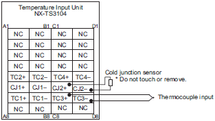
Temperature Input Unit (Thermocouple Input type) 4 points NX-TS3104

Unit name Temperature Input Unit
(thermocouple input type)
Model NX-TS3104
Number of points 4 points External connection
terminals
Screwless clamping terminal block
(16 terminals x 2)
I/O refreshing
method
Free-Run refreshing
Indicator TS indicator
3189_sp_10_1
Temperature sensor K, J, T, E, L, U, N, R, S, WRe5-26, PLII
Input conversion range ±20°C of the input range
Absolute maximum
rating
±130 mV
Input impedance 20 kΩ min.
Resolution 0.001°C max.
Reference accuracy *1
Temperature
coefficient
*1
Cold junction
compensation error
±1.2°C *2 *3
Input disconnection
detection current
Approx. 0.1 μA
Warm-up period 45 minutes Conversion time 60 ms/Unit
Dimensions 24 (W) x 100 (H) x 71 (D) Isolation method Between the input and the NX bus:
Power = Transformer, Signal = Digital
isolator
Between inputs: Power = Transformer,
Signal = Digital isolator
Insulation
resistance
20 MΩ min. between isolated
circuits (at 100 VDC)
Dielectric strength 510 VAC between isolated circuits for
1 minute at a leakage current of 5 mA
max.
I/O power supply
method
No supply Current capacity of
I/O power supply
terminal
Without I/O power supply terminals
NX Unit power
consumption
• Connected to a CPU Unit
1.45 W max.
• Connected to a Communi-
cations Coupler Unit
1.10 W max.
Current consumption
from I/O power supply
No consumption
Weight 140 g max.
Installation
orientation and
restrictions
Installation orientation:
• Connected to a CPU Unit: Possible in upright installation.
• Connected to a Communications Coupler Unit: Possible in 6 orientations.
Restrictions:
The cold junction compensation error is restricted according to the installation orientation and the
power consumption of adjacent Units. Refer to Cold Junction Compensation Error Specifications for
Units That Take a Thermocouple Input Type.
Terminal
connection
diagram
3189_sp_10_2

*1. Refer to Reference Accuracy and Temperature Coefficient According to the Input Type and Measurement
       Temperature.
*2. The overall accuracy is guaranteed for a set consisting of a cold junction sensor that is mounted on the terminal
       block and a Temperature Input Unit. Be sure to use the terminal block and the Temperature Input Unit together.
       A calibration control number is both displayed on the terminal block and the Unit. Make sure to return the terminal
       block (including a cold junction sensor mounted) and the Unit together for repair.
*3. Refer to Cold Junction Compensation Error Specifications for Units That Take a Thermocouple Input Type for the
       specifications for each set of operating conditions.

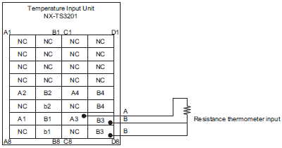
Temperature Input Unit (Resistance Thermometer Input type) 4 points NX-TS3201

Unit name Temperature Input Unit
(resistance thermometer
input type)
Model NX-TS3201
Number of points 4 points External connection
terminals
Screwless clamping terminal block
(16 Terminals x 2)
I/O refreshing
method
Free-Run refreshing
Indicator TS indicator
3189_sp_11_1
Temperature sensor Pt100 (three-wire)/Pt1000 (three-wire)
Input conversion
range
±20°C of the input range
Input detection
current
Approx. 0.25 mA
Resolution 0.1°C max.
Reference accuracy *
Temperature
coefficient
*
Effect of conductor
resistance
0.06°C/Ω max. (also 20 Ω max.)
Warm-up period 10 minutes Conversion time 250 ms/Unit
Dimensions 24 (W) x 100 (H) x 71 (D) Isolation method Between the input and the NX bus: Power
= Transformer, Signal = Photocoupler
Between inputs: Power = Transformer,
Signal = Photocoupler
Insulation
resistance
20 MΩ min. between isolated
circuits (at 100 VDC)
Dielectric strength 510 VAC between isolated circuits for 1
minute at a leakage current of 5 mA max.
I/O power
supply
method
No supply Current capacity of
I/O power supply
terminal
Without I/O power supply terminals
NX Unit power
consumption
• Connected to a CPU Unit
1.75 W max.
• Connected to a Communi-
cations Coupler Unit
1.30 W max.
Current consumption
from I/O power supply
No consumption
Weight 140 g max.
Installation
orientation
and restrictions
Installation orientation:
• Connected to a CPU Unit: Possible in upright installation.
• Connected to a Communications Coupler Unit: Possible in 6 orientations.
Restrictions: No restrictions
Terminal
connection
diagram
3189_sp_11_2

* Refer to Reference accuracy and temperature coefficient according to the input type and measurement temperature.

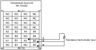
Temperature Input Unit (Resistance Thermometer Input type) 4 points NX-TS3202

Unit name Temperature Input Unit
(resistance thermometer
input type)
Model NX-TS3202
Number of points 4 points External connection
terminals
Screwless clamping terminal block
(16 Terminals x 2)
I/O refreshing
method
Free-Run refreshing
Indicator TS indicator
3189_sp_12_1
Temperature sensor Pt100 (three-wire)
Input conversion
range
±20°C of the input range
Input detection
current
Approx. 0.25 mA
Resolution 0.01°C max.
Reference accuracy *
Temperature
coefficient
*
Effect of conductor
resistance
0.06°C/Ω max. (also 20 Ω max.)
Warm-up period 30 minutes Conversion time 10 ms/Unit
Dimensions 24 (W) x 100 (H) x 71 (D) Isolation method Between the input and the NX bus: Power
= Transformer, Signal = Digital isolator
Between inputs: Power = Transformer,
Signal = Digital isolator
Insulation
resistance
20 MΩ min. between isolated
circuits (at 100 VDC)
Dielectric strength 510 VAC between isolated circuits for 1
minute at a leakage current of 5 mA max.
I/O power
supply
method
No supply Current capacity of
I/O power supply
terminal
Without I/O power supply terminals
NX Unit power
consumption
• Connected to a CPU Unit
1.50 W max.
• Connected to a Communi-
cations Coupler Unit
1.05 W max.
Current consumption
from I/O power supply
No consumption
Weight 130 g max.
Installation
orientation
and restrictions
Installation orientation:
• Connected to a CPU Unit: Possible in upright installation.
• Connected to a Communications Coupler Unit: Possible in 6 orientations.
Restrictions: No restrictions
Terminal
connection
diagram
3189_sp_12_2

* Refer to Reference accuracy and temperature coefficient according to the input type and measurement temperature.

Temperature Input Unit (Resistance Thermometer Input type) 4 points NX-TS3204

Unit name Temperature Input Unit
(resistance thermometer
input type)
Model NX-TS3204
Number of points 4 points External connection
terminals
Screwless clamping terminal block
(16 Terminals x 2)
I/O refreshing
method
Free-Run refreshing
Indicator TS indicator
3189_sp_13_1
Temperature sensor Pt100 (three-wire)/Pt1000 (three-wire)
Input conversion
range
±20°C of the input range
Input detection
current
Approx. 0.25 mA
Resolution 0.001°C max.
Reference accuracy *
Temperature
coefficient
*
Effect of conductor
resistance
0.06°C/Ω max. (also 20 Ω max.)
Warm-up period 30 minutes Conversion time 60 ms/Unit
Dimensions 24 (W) x 100 (H) x 71 (D) Isolation method Between the input and the NX bus: Power
= Transformer, Signal = Digital isolator
Between inputs: Power = Transformer,
Signal = Digital isolator
Insulation
resistance
20 MΩ min. between isolated
circuits (at 100 VDC)
Dielectric strength 510 VAC between isolated circuits for 1
minute at a leakage current of 5 mA max.
I/O power
supply
method
No supply Current capacity of
I/O power supply
terminal
Without I/O power supply terminals
NX Unit power
consumption
• Connected to a CPU Unit
1.45 W max.
• Connected to a Communi-
cations Coupler Unit
1.05 W max.
Current consumption
from I/O power supply
No consumption
Weight 130 g max.
Installation
orientation
and restrictions
Installation orientation:
• Connected to a CPU Unit: Possible in upright installation.
• Connected to a Communications Coupler Unit: Possible in 6 orientations.
Restrictions: No restrictions
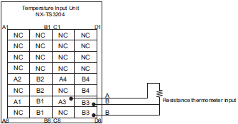
Terminal
connection
diagram
3189_sp_13_2

* Refer to Reference accuracy and temperature coefficient according to the input type and measurement temperature.

Reference accuracy and temperature coefficient according to the input type and measurement temperature *1

For NX-TS[][]02/TS[][]04

Conversion
time
Input type Measured
temperature (°C)
Reference
accuracy °C (%)
*3
Temperature
coefficient °C/°C *4
Input (ppm/°C *5)
Input
type *2
Temperature
range (°C)
10/60 ms K -200 to 1300 Same as the left ±0.75 (±0.05%) ±0.08 (±50 ppm/°C)
K -20 to 600
(High Resolution)
Same as the left ±0.30 (±0.05%) ±0.03 (±48 ppm/°C)
J -200 to 1200 -200 to 0 ±0.70 (±0.05%) ±0.13 (±96 ppm/°C)
0 to 1200 ±0.06 (±42 ppm/°C)
J -20 to 600
(High Resolution)
Same as the left ±0.30 (±0.05%) ±0.04 (±72 ppm/°C)
T -200 to 400 -200 to -180 ±1.30 (±0.22%) ±0.05 (±75 ppm/°C)
-180 to 0 ±0.70 (±0.12%)
0 to 400 ±0.33 (±0.055%)
E -200 to 1000 -200 to 0 ±0.60 (±0.05%) ±0.12 (±100 ppm/°C)
0 to 1000 ±0.06 (±50 ppm/°C)
L -200 to 900 Same as the left ±0.50 (±0.05%) ±0.04 (±40 ppm/°C)
U -200 to 600 -200 to -100 ±0.70 (±0.09%) ±0.06 (±75 ppm/°C)
-100 to 0 ±0.50 (±0.07%)
0 to 600 ±0.40 (±0.05%)
N -200 to 1300 -200 to -150 ±1.60 (±0.11%) ±0.11 (±70 ppm/°C)
-150 to -100 ±0.75 (±0.05%)
-100 to 1300 ±0.08 (±50 ppm/°C)
R -50 to 1700 -50 to 0 ±3.20 (±0.19%) ±0.13 (±77 ppm/°C)
0 to 100 ±2.50 (±0.15%) ±0.11 (±60 ppm/°C)
100 to 1700 ±1.75 (±0.10%)
S -50 to 1700 -50 to 0 ±3.20 (±0.19%) ±0.13 (±77 ppm/°C)
0 to 100 ±2.50 (±0.15%) ±0.11 (±60 ppm/°C)
100 to 1700 ±1.75 (±0.10%)
WRe5-26 0 to 2300 0 to 1500 ±1.15 (±0.05%) ±0.13 (±58 ppm/°C)
1500 to 2200 ±0.21 (±91 ppm/°C)
2200 to 2300 ±1.40 (±0.07%)
PL II 0 to 1300 Same as the left ±0.65 (±0.05%) ±0.07 (±57 ppm/°C)
Pt100 -200 to 850 -200 to -50 ±0.50 (±0.05%) ±0.08 (±78 ppm/°C)
-50 to 150 ±0.21 (±0.02%) ±0.03 (±29 ppm/°C)
150 to 850 ±0.50 (±0.05%) ±0.08 (±78 ppm/°C)
Pt1000 -200 to 850 Same as the left ±0.50 (±0.05%) ±0.09 (±85 ppm/°C)

For NX-TS[][]01

Conversion
time
Input type Measured
temperature (°C)
Reference
accuracy °C (%)
*3
Temperature
coefficient °C/°C *4
Input (ppm/°C *5)
Input
type
Temperature
range (°C)
250 ms K -200 to 1300 -200 to -100 ±1.5 (±0.1%) ±0.15 (±100 ppm/°C)
-100 to 400 ±0.30 (±200 ppm/°C)
400 to 1300 ±0.38 (±250 ppm/°C)
J -200 to 1200 -200 to 400 ±1.4 (±0.1%) ±0.14 (±100 ppm/°C)
400 to 900 ±1.2 (±0.09%) ±0.28 (±200 ppm/°C)
900 to 1200 ±0.35 (±250 ppm/°C)
T -200 to 400 -200 to -100 ±1.2 (±0.2%) ±0.30 (±500 ppm/°C)
-100 to 400 ±0.12 (±200 ppm/°C)
E -200 to 1000 -200 to 400 ±1.2 (±0.1%) ±0.12 (±100 ppm/°C)
400 to 700 ±2.0 (±0.17%) ±0.24 (±200 ppm/°C)
700 to 1000 ±0.30 (±250 ppm/°C)
L -200 to 900 -200 to 300 ±1.1 (±0.1%) ±0.11 (±100 ppm/°C)
300 to 700 ±2.2 (±0.2%) ±0.22 (±200 ppm/°C)
700 to 900 ±0.28 (±250 ppm/°C)
U -200 to 600 -200 to 400 ±1.2 (±0.15%) ±0.12 (±150 ppm/°C)
400 to 600 ±1.0 (±0.13%)
N -200 to 1300 -200 to 400 ±1.5 (±0.1%) ±0.30 (±200 ppm/°C)
400 to 1000
1000 to 1300 ±0.38 (±250 ppm/°C)
R -50 to 1700 -50 to 500 ±1.75 (±0.1%) ±0.44 (±250 ppm/°C)
500 to 1200 ±2.5 (±0.15%)
1200 to 1700
S -50 to 1700 -50 to 600 ±1.75 (±0.1%) ±0.44 (±250 ppm/°C)
600 to 1100 ±2.5 (±0.15%)
1100 to 1700
B 0 to 1800 0.0 to 400.0 Reference accuracy
does not apply
Reference accuracy does
not apply
400 to 1200 ±3.6 (±0.2%) ±0.45 (±250 ppm/°C)
1200 to 1800 ±5.0 (±0.28%) ±0.54 (±300 ppm/°C)
WRe5-26 0 to 2300 0 to 300 ±1.15 (±0.05%) ±0.46 (±200 ppm/°C)
300 to 800 ±2.3 (±0.1%)
800 to 1500 ±3.0 (±0.13%)
1500 to 2300 ±0.691 (±300 ppm/°C)
PLII 0 to 1300 0 to 400 ±1.3 (±0.1%) ±0.23 (±200 ppm/°C)
400 to 800 ±2.0 (±0.15%) ±0.39 (±300 ppm/°C)
800 to 1300 ±0.65 (±500 ppm/°C)
Pt100 -200 to 850 -200 to 300 ±1.0 (±0.1%) ±0.1 (±100 ppm/°C)
300 to 700 ±2.0 (±0.2%) ±0.2 (±200 ppm/°C)
700 to 850 ±2.5 (±0.25%) ±0.25 (±250 ppm/°C)
Pt1000 -200 to 850 -200 to 300 ±1.0 (±0.1%) ±0.1 (±100 ppm/°C)
300 to 700 ±2.0 (±0.2%) ±0.2 (±200 ppm/°C)
700 to 850 ±2.5 (±0.25%) ±0.25 (±250 ppm/°C)

*1. To convert the temperature unit from Celsius to Fahrenheit, use the following equation.
       Fahrenheit temperature (°F) = Celsius temperature (°C) x 1.8 + 32
*2. If there is more than one input range for the same input type, the one with narrower input range has higher
       resolution.
*3. For a thermocouple input type Temperature Input Unit, the overall accuracy is guaranteed for a set consisting of a
       cold junction sensor that is mounted on the terminal block and a Temperature Input Unit. Be sure to use the terminal
       block and Temperature Input Unit with the same calibration control number together. For the 24 mm wide model,
       also be sure the left and right terminal blocks are correctly attached.

NX-TS Specifications 31

*4. An error for a measured value when the ambient temperature changes by 1°C.
       The following formula is used to calculate the error of the measured value.
       Overall accuracy = Reference accuracy + Temperature characteristic x Change in the ambient temperature + Cold
       junction compensation error (Calculation example)
       Conditions

Item Description
Ambient temperature 30°C
Measured value 100°C
NX Unit NX-TS2101
Thermocouple K thermocouple

The characteristic values are formulated from the data sheet or reference accuracy and temperature coefficient table under the above conditions

Item Description
Reference accuracy -100 to 400°C: ±1.5°C
Temperature coefficient -100 to 400°C: ±0.30°C/°C
Change in the ambient temperature 25°C -> 30°C 5 deg
Cold junction compensation error ±1.2°C

Therefore,
Overall accuracy = Reference accuracy + Temperature characteristic x Change in the ambient temperature + Cold junction compensation error
= ±1.5°C + (±0.30°C/°C) x 5 deg + ±1.2°C
= ±4.2°C

*5. The ppm value is for the full scale of temperature range.

Cold Junction Compensation Error Specifications for Units That Take a Thermocouple Input Type

The cold junction compensation error for Units that take a thermocouple input type is restricted as follows according to the installation orientation and the power consumption of adjacent Units *.

(a) For upright installation, when the power consumption is 1.5 W or less for both the left and right adjacent Units
       The cold junction compensation error is ±1.2°C.
       However, there are exceptions depending on the input type and temperature. Those conditions and the cold junction
       compensation error are as in the table below.

Input type and temperature range Cold junction compensation error
T below -90°C ±3.0°C
J, E, K and N below -100°C
U, L and PLII
R and S below 200°C
B below 400°C Not guaranteed
W ±3.0°C

(b) When the power consumption of either the left or the right adjacent Unit is more than 1.5 W but less than 3.9 W. Or
       for any installation other than upright, when the power consumption of both the left and right adjacent Units is less
       than 3.9 W
       The cold junction compensation error is ±4.0°C.
       However, there are exceptions depending on the input type and temperature. Those conditions and the cold junction
       compensation error are as in the table below.

Input type and temperature range Cold junction compensation error
T below -90°C ±7.0°C
J, E, K and N below -100°C
U, L and PLII
R and S below 200°C
B below 400°C Not guaranteed
W ±9.0°C

(c) When the power consumption exceeds 3.9 W for either the left or right adjacent Unit
       Do not use the above condition (c) because the cold junction compensation error is not guaranteed in this condition.

* The power consumption of adjacent Units is the total of the following values.
    The power consumption of the NX Unit power supply and I/O power supply for the NX Units adjacent to the
    Temperature Input Unit. If the adjacent Unit is an Input Unit, it is the total power consumption according to the input
    current.

Version Information

Connecting with CPU Units

Refer to the user's manual for the CPU Unit for the CPU Unit to which NX Units can be connected.

NX Units Corresponding version *
Model Unit Version CPU Unit Sysmac Studio
NX-TS2101 Ver.1.0 Ver.1.13 or later Ver.1.17 or higher
Ver.1.1
NX-TS2102 Ver.1.1
NX-TS2104 Ver.1.1
NX-TS2201 Ver.1.0
Ver.1.1
NX-TS2202 Ver.1.1
NX-TS2204 Ver.1.1
NX-TS3101 Ver.1.0
Ver.1.1
NX-TS3102 Ver.1.1
NX-TS3104 Ver.1.1
NX-TS3201 Ver.1.0
Ver.1.1
NX-TS3202 Ver.1.1
NX-TS3204 Ver.1.1

* Some Units do not have all of the versions given in the above table. If a Unit does not have the specified version, support
   is provided by the oldest available version after the specified version. Refer to the user's manuals for the specific Units
   for the relation between models and versions.

Connecting with Coupler Units

NX Units Corresponding version *
Model Unit
Version
EtherCAT Ethernet/IP
Communica-
tions
Coupler Unit
NJ/NX-series CPU
Units or NY-series
Industrial PCs
Sysmac Studio Communica-
tions
Coupler Unit
Sysmac Studio
NX-TS2101 Ver.1.0 Ver.1.0 or later Ver.1.05 or later Ver.1.06 or higher Ver.1.0 or later Ver.1.10 or higher
Ver.1.1 Ver.1.08 or higher
NX-TS2102 Ver.1.1 Ver.1.08 or higher
NX-TS2104 Ver.1.1 Ver.1.08 or higher
NX-TS2201 Ver.1.0 Ver.1.06 or higher
Ver.1.1 Ver.1.08 or higher
NX-TS2202 Ver.1.1 Ver.1.08 or higher
NX-TS2204 Ver.1.1 Ver.1.08 or higher
NX-TS3101 Ver.1.0 Ver.1.06 or higher
Ver.1.1 Ver.1.08 or higher
NX-TS3102 Ver.1.1 Ver.1.08 or higher
NX-TS3104 Ver.1.1 Ver.1.08 or higher
NX-TS3201 Ver.1.0 Ver.1.06 or higher
Ver.1.1 Ver.1.08 or higher
NX-TS3202 Ver.1.1 Ver.1.08 or higher
NX-TS3204 Ver.1.1 Ver.1.08 or higher

* Some Units do not have all of the versions given in the above table. If a Unit does not have the specified version, support
   is provided by the oldest available version after the specified version. Refer to the user’s manuals for the specific Units
   for the relation between models and versions.