| Power supply voltage | No D in model number: 100 to 240 VAC, 50/60 Hz
D in model number: 24 VAC, 50/60 Hz; 24 VDC |
|
|---|---|---|
| Operating voltage range | 85% to 110% of rated supply voltage | |
| Power consumption | 100 to 240 VAC: 8.5 VA (max.) (E5CN-HTR2 at 100 VAC: 3.0 VA)
24 VAC/VDC: 5.5 VA (24 VAC)/3.5 W (24 VDC) (max.) (E5CN-HTR2D at 24 VAC: 2.7 VA) |
|
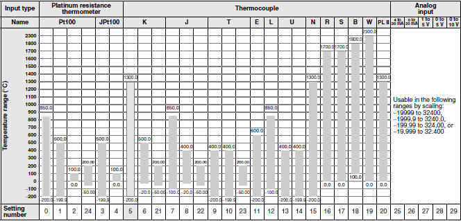
| Sensor input | Any of the following can be selected (i.e., fully universal input).
Thermocouple: K, J, T, E, L, U, N, R, S, B, W, or PL II Platinum resistance thermometer: Pt100 or JPt100 Current input: 4 to 20 mA or 0 to 20 mA Voltage input: 1 to 5 V, 0 to 5 V, or 0 to 10 V |
|
| Input impedance | Current input: 150 Ω max., Voltage input: 1 MΩ min. (Use a 1:1 connection when connecting the
ES2-HB.) |
|
| Control method | ON/OFF control or 2-PID control (with auto-tuning) | |
| Control
output |
Relay output | SPST-NO, 250 VAC, 3 A (resistive load), electrical life: 100,000 operations,
minimum applicable load: 5 V, 10 mA |
| Voltage output
(for driving SSR) |
Output voltage: 12 VDC ± 15% (PNP), max. load current: 21 mA, with short-circuit protection circuit | |
| Current output | 4 to 20 mA DC/0 to 20 mA DC, load: 600 Ω max., resolution: approx. 10,000 * | |
| Linear voltage output | 0 to 10 VDC (load: 1 kΩ min.), Resolution: Approx. 10,000 | |
| Auxiliary
output |
Number of outputs | 2 max. |
| Output specifications | Relay output: SPST-NO, 250 VAC, 3 A (resistive load), electrical life: 100,000 operations, minimum
applicable load: 5 V, 10 mA |
|
| Event
input |
Number of outputs | 2 |
| External contact
input specifications |
Contact input: ON: 1 kΩ max., OFF: 100 kΩ min. | |
| Non-contact input: ON: Residual voltage: 1.5 V max., OFF: Leakage current: 0.1 mA max. | ||
| Current flow: Approx. 7 mA per contact | ||
| Logic
operations |
Number of operations | 8 max. (Combinations can be made using work bits.) |
| Operations | Logic operation:
Any of the following four patterns can be selected. The input status may be inverted. (A and B) or (C and D), (A or C) and (B or D), A or B or C or D, A and B and C and D (A, B, C, and D are four inputs.) Delay: ON delay or OFF delay for the results of the logic operation given above. Setting time: 0 to 9999 s or 0 to 9999 min Output inversion: Possible |
|
| Outputs | One work bit per operation | |
| Work bit assignments | Any of the following can be assigned to up to eight work bits (logic operation results): Operation
commands (assigned to event inputs) *, auxiliary outputs, or control outputs. * Application is possible with models that do not have event inputs by using an internal assignment. |
|
| Transfer
outputs |
Number of outputs | 1 max. |
| Output specifications | Current output: 4 to 20 mA DC, Load: 600 Ω max., Resolution at 4 to 20 mA: Approx. 10,000 | |
| RSP input | Not supported | |
| Setting method | Digital setting using front panel keys | |
| Indication method | 11-segment digital display and individual indicators (7-segments displays also possible)
Character height: PV: 11 mm, SV: 6.5 mm |
|
| Other functions | Manual output, heating/cooling control, loop burnout alarm, other alarm functions, heater burnout
detection (including SSR failure and heater overcurrent detection), 40% AT, 100% AT, MV limiter, input digital filter, temperature input shift, run/reset, protection functions, control output ON/OFF counter, extraction of square root, MV change rate limit, PV/SV status display, automatic cooling coefficient adjustment, program control functions, etc. |
|
| Ambient operating temperature | -10 to 55 ° C (with no condensation or icing), for 3-year warranty: -10 to 50 ° C | |
| Ambient operating humidity | 25% to 85% | |
| Storage temperature | -25 to 65 ° C (with no condensation or icing) | |


