

| Model | XW5T-P1.5-1.1-1 (BL) | XW5T-P2.5-1.1-1 (BL) | XW5T-P4.0-1.1-1 (BL) | ||||
|---|---|---|---|---|---|---|---|
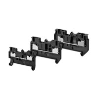
| Appearance and internal
wiring |
1 tier, 1:1
 |
1 tier, 1:1
 |
1 tier, 1:1
 |
||||
| Applicable
wire sizes |
NOMINAL CROSS
SECTION |
1.0 mm2 (1.25 mm2)* | 2.5 mm2 | 4 mm2 | |||
| Minimum conductor
cross section solid |
0.14 mm2 | 0.14 mm2 | 0.2 mm2 | ||||
| Maximum conductor
cross section solid |
1.5 mm2 | 4.0 mm2 | 6.0 mm2 | ||||
| Minimum conductor
cross section fine stranded |
0.08 mm2 | 0.14 mm2 | 0.2 mm2 | ||||
| Maximum conductor
cross section fine stranded |
1.5 mm2 | 2.5 mm2 | 4.0 mm2 | ||||
| Minimum conductor
cross section (flex., stranded) with ferrule with Plastic sleeve |
0.14 mm2 | 0.14 mm2 | 0.2 mm2 | ||||
| Maximum conductor
cross section (flex., stranded) with ferrule with Plastic sleeve |
1.0 mm2 (1.25 mm2)* | 2.5 mm2 | 4.0 mm2 | ||||
| Conductor cross
section AWG |
AWG28 to AWG14 | AWG26 to AWG12 | AWG24 to AWG10 | ||||
| Wire strip length | 8 mm | 10 mm | 12 mm | ||||
| Dimensions | 3.5×45×30.5 | 5.2×48.8×35.25 | 6.2×56.1×35.25 | ||||
| IEC rated voltage | 500 V | 800 V | 800 V | ||||
| IEC rated current | 17.5 A/1.5 mm2 (SOL), 13.5 A/1.0 mm2
(STR) |
24 A/2.5 mm2 (SOL), 17.5 A/1.5 mm2
(STR) |
32 A/4.0 mm2 (SOL), 24 A/2.5 mm2 (STR) | ||||
| Usage Group (UG) | B, C | D | B, C | ||||
| UL rated voltage | 300 V | 51-150 V | 151-300 V | 301-600 V | 600 V | ||
| UL rated current | 15 A (SOL)
10 A (STR) |
15 A (SOL)
10 A (STR) |
10 A | 5 A | 20 A/AWG12 (SOL), 15 A/AWG14 (STR) | 30 A/AWG10 (SOL), 20 A/AWG12 (STR) | |
| Dielectric strength | 1,890 VAC for 1 min
(leakage current: 1 mA max.) |
2,000 VAC for 1 min
(leakage current: 1 mA max.) |
2,000 VAC for 1 min
(leakage current: 1 mA max.) |
||||
| End Cover | XW5E-P1.5-1.1-1 | XW5E-P2.5-1.1-1 | XW5E-P4.0-1.1-1 | ||||
| Special tool | XW4Z-00B | XW4Z-00B | XW4Z-00B | ||||
| Applicable nameplates | XW5Z-P1.5LB[] or commercially available nameplate with 9.5 mm width and 0.5 mm thickness | XW5Z-P2.5LB[] or commercially available nameplate with 9.5 mm width and 0.5 mm thickness | XW5Z-P4.0LB[] or commercially available nameplate with 9.5 mm width and 0.5 mm thickness | ||||
| Applicable Short Bars | XW5S-P1.5-[]
([]: Poles = 2, 3, 4, 5 or 10) |
XW5S-P2.5-[]
([]: Poles = 2, 3, 4, 5 or 10) |
XW5S-P4.0-[]
([]: Poles = 2, 3, 4, 5 or 10) |
||||


