inverters
OMRON Inverters support energy-saving operation of facilities and machines with fine speed control. Models with DeviceNet communications are also provided. Concerning Frequency Inverters, OMRON offers different products in different areas. So please click on the banner "Products links" in the top right corner to reach the country website nearest you.
|
|
Features |
| Principles | Classifications |
| Engineering Data | Further Information |
|
|
Troubleshooting |
Simplified Selection Method (Required Output Calculation)
This method of calculation helps you select a motor by calculating the output (kW) required by the motor to maintain its steady rotations. To use this method for motor selection, make allowance for the calculated result because it does not include acceleration/deceleration and other transient state calculations. The simplified selection method is suitable for fan, conveyor, mixer, and other applications where a constant state continues for a while.
The simplified selection method cannot be used for the following applications. For these applications, use the detailed selection method.
Those requiring rapid startup (acceleration)
Those that frequently repeat run and stop
Those that have a large inertia at the power transfer part
Those that have an inefficient power transfer part
For linear motion: Steady power P0 [kW]

For rotation motion: Steady power P0 [kW]

Detailed Selection Method (RMS Calculation)
This method helps you select a motor by calculating the effective torque and maximum torque values required to achieve a certain pattern of operation for the application.
It selects a motor that is optimal for a particular operation pattern.
Calculation of motor-shaft conversion torque and effective torque
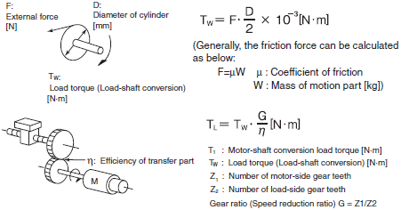
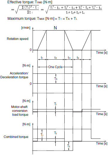
Calculate the acceleration torque from the motor-shaft conversion load inertia, the motor-rotor inertia, and the acceleration. Then, calculate the load torque from the external force (gravity and tension) and friction force applied to the load. Finally, combine these calculation results to calculate the torque required for the motor.
Calculation of acceleration torque

Calculation of motor-shaft conversion load torque

Calculation of combined torque and effective torque

Motor selection
Based on the above calculation results, select the motor capacity by using the following formulae.
Select the larger of the two calculated values as the motor capacity.
Also, when selecting a motor, take into consideration the errors in calculation and modeling. Select a motor whose capacity is at least approximately 20% larger.
Motor capacity conversion to effective torque
Motor capacity [kW] = 1.048·N·TRMS·10-4
N: Maximum rotation speed [r/min]
Motor capacity required for maximum torque output
Motor capacity [kW] = 1.048·N·TMAX·10-4/1.5
N: Maximum rotation speed [r/min]
Inverter Capacity Selection
Select an inverter that can be used with the motor you selected based on the result of motor capacity selection.
Basically, select an inverter which fits the maximum applicable motor capacity of the selected motor.
After selecting an inverter, check if it meets the both of the following conditions. If not, select an inverter with one size larger in capacity and check again.
Rated motor current ≤ Rated output current of inverter
Max. continuous torque output time for application ≤ 1 min
Note 1:If the inverter overload capacity is 120% of the rated output current for 1 minute, check it for 0.8 minute.
Note 2:If you want to use 0-Hz sensorless vector control, need a holding torque at a rotation speed of 0 (r/min), or frequently require 150% of the rated torque or more, use an inverter with one size larger in capacity than the one selected by the above method.
[[Overview of Braking Resistor Selection]]
Requirement of Braking Resistor
If the regenerative energy generated in deceleration or descent in an application is too large, the main circuit voltage in the inverter may increase, which results in damage to the inverter.
Normally, the inverter has a built-in overvoltage protection function, which detects an overvoltage (0 V) in the main circuit to prevent inverter damage.
However, because it detects a fault to stop the motor, stable and continuous operation will be prevented.
Therefore, you need to use one or more braking resistors/regenerative braking units to absorb this regenerative energy outside the inverter.
What is Regenerative Energy?
The load connected to a motor has kinetic energy when rotating, and potential energy when it is subject to the gravity.
When the motor decelerates, or when the load descends, the energy is fed back to an inverter.
This phenomenon is known as regeneration, and the energy is called regenerative energy.

Preventing an overvoltage (0 V) in the main circuit without use of braking resistors
The following are methods to prevent the occurrence of an overvoltage (0 V) in the main circuit without connection of braking resistors.
Since these methods prolong the deceleration time, check that the selected method will not cause application problems.
Enable the Overvoltage Suppression Function during Deceleration (It is enabled by default.) (It automatically increases the deceleration time to prevent the occurrence of an Overvoltage in the main circuit.)
Set a longer deceleration time (This decreases the amount of regenerative energy per unit time.)
Select free-run stop (This prevents the regenerative energy from being fed back to the inverter.)
Simplified Braking Resistor Selection
This is a simple method to select an appropriate braking resistor based on the percentage of the time in which regenerative energy is produced in a normal operation pattern. Calculate the usage rate from the following operating pattern.

Detailed Braking Resistor Selection
When the usage rate of the braking resistor selected on the previous page exceeds 10% ED, or when an extremely large braking torque is required, use the method below to calculate a regenerative energy and make your selection.
Calculation of required braking resistance

Note:Calculate a braking torque according to Inverter Capacity Selection in the Motor Capacity Selection section.
Calculation of average regenerative energy
Regenerative energy is produced when the motor rotation and the torque are opposite in direction.
Use the following formula to calculate the regenerative energy for each period in a cycle.

Note 1:For Speed, the forward rotation direction is indicated as positive. For Torque, the torque in the forward rotation direction is indicated as positive.
Note 2:Calculate a braking torque according to Inverter Capacity Selection in the Motor Capacity Selection section.
Braking Resistor Selection
Select a braking resistor from the required braking resistance and the average regenerative energy described on the left section.
Required braking resistance ≥ Resistance of braking resistor ≥ Min. connection resistance of inverter or regenerative braking unit
Average regenerative energy ≤ Resistance capacity of braking resistor
Note 1:Connecting a braking resistor whose resistance is less than the minimum connection resistance value of the inverter or regenerative braking unit results in damage to the internal braking transistor. If the required braking resistance is less than the minimum connection resistance, change the inverter or regenerative braking unit to one having a larger capacity and ensure that the required braking resistance is not less than the minimum connection resistance.
Note 2:Two or more regenerative braking units can be connected in parallel. Refer to the following formula to know the braking resistance value in such a case:
braking resistance (Ω) = (Required braking resistance calculated as above) ✕ (No. of units)
Note 3:Make allowance for the resistance capacity of the braking resistor. Select a braking resistor whose capacity is at least 20% larger than the calculated value. Otherwise, it may be overheated.


