Pressure Sensors
|
|
Features |
|
|
Classifications |
| Engineering Data |
|
| Explanation of Terms | Troubleshooting |
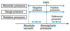
The amount of pressure is expressed in terms of atmospheric pressure. It is referred to as "positive pressure" when it is greater than one atmosphere, and "negative pressure" when it is less than one atmosphere.
Absolute Pressure
This is the amount of pressure expressed in relation to an absolute vacuum.
Pressure Difference (Relative Pressure)
This is the amount of pressure compared to any particular pressure (the reference pressure).

The pressure of the atmosphere. The standard atmospheric pressure (1 atm) is equal to the pressure of a column of mercury with a height of 760 mm.
Vacuum
A pressure less than one atmosphere.
The range of pressure that can be detected by the Sensor.
The pressure that must be withstood without degraded performance after returning to the pressure detection range.
Repeat Accuracy (ON/OFF Output)
Repeat accuracy refers to the deviation in the operating point when the output inverts while pressure is increased or decreased at a temperature of 23°C, divided by the full scale of the pressure detection range.

Accuracy (linear)
This is the deviation from the rated output current (4 mA, 20 mA) when zero pressure and the rated output are applied at a temperature of 23°C, divided by the full-scale value.
It is expressed in units of %F.S.
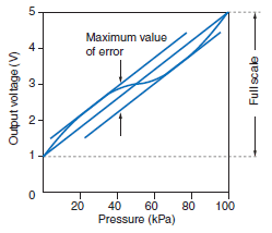
The analog output changes in an approximately linear fashion with respect to the detected pressure. The change, however, deviates slightly from an ideal straight line. This deviation is expressed as a percentage of the full scale.

Linear Hysteresis
An ideal straight line is drawn between the output current (or voltage) at zero pressure and the rated current (or voltage), and the difference between the measured current (or voltage) and the ideal current (voltage) is obtained as an error. The error as the pressure rises and the error as the pressure falls are obtained, and the maximum value of the absolute value of the difference between the rising error and falling error is divided by the full scale current (or voltage). This is the linear hysteresis, and it is expressed in units of %FS.
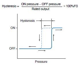
Hysteresis (ON/OFF Output)
The difference between the output ON pressure and OFF pressure is divided by the full pressure scale.

Non-corrosive Gas
Substances contained in the air (nitrogen, carbon dioxide, etc.) and inert gases (argon, neon, etc.).
Pressure Unit Conversion Table
| kgf/cm2 | mmHg | mmH2O | Pa | |
| 1kgf/cm2 | 1 | 735.559 | 1.000028×10⁴ | 0.0980665M |
| 1mmHg | 1.3595×10⁻³ | 1 | 1.3595×10 | 0.133322k |
| 1mmH2O | 0.99997×10⁻⁴ | 7.356×10⁻² | 1 | 0.00980665k |
| 1Pa (N/m2) | 1.0197×10⁻⁵ | 7.5006×10⁻³ | 0.10197 | 1 |
Output Impedance
1. Measuring the Output Impedance of Voltage Output Models
Figure 1

Ro: Output impedance [Ω]
Rx: Load resistance [Ω]
Eo: Output voltage (terminals open) [V]
Ex: Output voltage (with load Rx connected) [V]
Ix: Load current (with load Rx connected) [A]
In Figure 1, the current (Ix) that flows when the load resistance (Rx) is connected is calculated as follows:

The output impedance (Ro) in Equation (1) is calculated as follows:

The voltage (Eo) is measured when the output is open, followed by the voltage (Ex) when a load resistance (for example, the minimum value of the permitted load resistance of a transducer) is connected. The measured values Eo and Ex and the connected load resistance (Rx) are inserted into Equation (2) to calculate the output impedance (Ro) of the transducer.
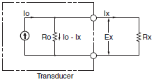
2. Measuring the Output Impedance of Current Output Models
In Figure 2, the voltage (Ex) of the output terminals when the load resistance (Rx) is connected is calculated as follows:
Ex = IxRx = (Io - Ix) Ro ......(3)
The output impedance in Equation (3) is calculated as follows:

Here, the current (Io) is measured with the output shortcircuited.
Figure 2

Ro: Output impedance [Ω]
Rx: Load resistance [Ω]
Io: Output current (output terminal short-circuited) [A]
Ix: Output current (with load Rx connected) [A]
Ex: Output voltage (with load Rx connected) [V]
Next, the output current (Ix) is measured when a load resistance (for example, the maximum value of the permitted load resistance of a transducer) is connected. The measured values Io and Ix and the value of the connected load resistance (Rx) are inserted into Equation (4), and the output impedance (Ro) of the transducer is calculated. The output impedance of the transducer introduced here is the value for normal operation.
3. Desirable Output Impedance
In general, it is best to make the output impedance of a voltage output transducer as small as possible, i.e., as close to 0 W as possible, to minimize the effects of load fluctuations on the transducer.
For a current output transducer, the opposite is true: the higher the impedance (the closer to infinite impedance), the better.
4. Example of Calculation Using Impedance


| Rx | Error |
| 1kΩ | Approximately 10% |
| 10kΩ | Approximately 1% |


