Question
Why can't an SE Motor Protective Relay be used in circuits containing thyristor control or a rectifier?
Answer
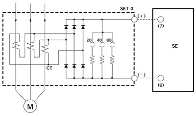
A schematic diagram showing the operating principle for the SE is shown below.

As shown in the above diagram, the waves for all three phases of the motor current from the CT of the SET-3A (3B) are rectified, then converted to DC voltage, which is necessary for the SE, by the resistor at each tap, and output from the positive and negative terminals. The DC and AC component ratios in this voltage differ between the normal three-phase condition and conditions of phase-failure or imbalance.

For the overload factor, the DC average level is detected relative to the set value. For the phase-failure factor, the proportion of the DC average level and AC component is used to distinguish phase failure or imbalance.
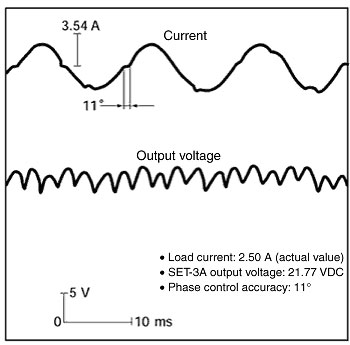
When the motor is operated using thyristor phase control, the motor current waveform is not a sine wave. The SE detects this as an adverse condition and initiates unnecessary operations. The example below shows a primary current and SET-3 output waveform. When there is a large AC component in the output voltage, the SE series sometimes judges it to be a phase-failure and initiates unnecessary operations.


