Question
What is the procedure for manually adjusting gain when using a Servomotor?
Answer
Perform the following procedures to adjust the gain.
1. Speed Loop Adjustment
Speed loop proportional gain
Speed loop integral gain (speed loop integral time constant)
Current loop command filter
Generally, basic adjustments can be performed using only proportional and integral gain, but vibration may not stop depending on the mechanical system or positioning may be delayed because the gain is low even if the vibration does stop. If this occurs, adjust the current loop filter time constant.
2. Position Loop Adjustment
Position loop proportional gain
This adjustment is used with a pulse train input. It is not relevant to an analog input.
Relation between Gain and Response:
1.Speed Loop Adjustment
The following graph shows how the response of the servo system (i.e., frequency characteristics) changes when the speed loop gain and adjustment parameters are changed.

In this graph, the horizontal axis represents the frequency (i.e., movement speed) and the vertical axis represents the strength of the corrective ability (i.e., the ability to have error approach zero).
(1) Speed Loop Proportional Gain
Response is changed across all frequency ranges.
Increasing the gain increases corrective strength and response speed.
Increase the level until the mechanical system does not vibrate.
(2) Speed Loop Integral Gain
Response is changed at low frequencies.
Increasing the gain increases servo lock strength.
Increase the level until the mechanical system does not vibrate.
(With the U Series, decrease the speed loop integral time constant.)
(3) Current Command Filter
Response is changed at high frequencies.
Increasing the filter time constant makes sudden command changes smoother before they are delivered to the current loop.
This adjustment is effective when there is mechanical system resonance and adjustment cannot be performed using only speed loop proportional gain or integral gain.
Adjustment Example 1
The following figures show a normal adjustment example (if there is no vibration at initial settings).
Adjustment is performed for proportional gain and then integral gain.

Adjustment Example 2
The following figures show an example of adjustment when there is a point of large mechanical system resonance in a high frequency range. The conditions are a low gain setting, humming motor, and generating a high-frequency vibration.
Adjustment is performed for current command filter time constant and then for integral gain. Resonance with the mechanical system can be avoided by increasing the current command filter time constant. Afterwards, perform the adjustment as normal adjustments are performed.

Adjustment Example 3
The following figures show an example of an adjustment when is a large point of mechanical system resonance in a low frequency range. The conditions are a low gain setting and generating a low-frequency vibration.

Changing Response Using Speed Loop Adjustment
The following figure shows the servo system response (time axis) when the speed loop gain and the adjustment parameters are changed.
Speed Loop Proportional Gain and Response

Speed Loop Integral Gain and Response

2.Position Loop Adjustment
The position loop is adjusted after the speed loop adjustment has been completed.
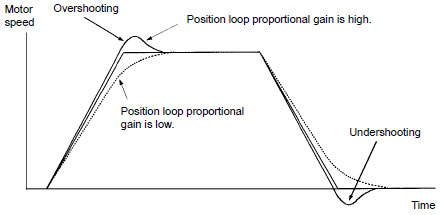
Response improves when position loop proportional gain is increased as long as overshooting or undershooting does not occur.
Position Loop Proportional Gain and Response

Overshooting and undershooting can be checked by using an oscilloscope to measure the voltage output at the motor speed (NM) terminal.
If no measuring equipment is available, check the movement of the motor shaft or mechanical system visually. If there is undershooting, perform positioning when the motor is stopped in the opposite direction of the rotating direction (as in the following figures).

The amount overshooting and undershooting depends on the rotating speed of the motor. Normally, the amount of overshooting and undershooting increases as the rotating speed increases. Therefore, it is recommended to perform adjustment using the maximum rotating speed.
Recommended Products
 CS1W-NC[]71
Decrease TCO with Simple Operation, Reduced Wiring, Batch Settings, and Batch Management
 CJ2
CJ2
Introducing the Flagship CJ2 CPU Units, with Built-in Multifunctional Ethernet Port.


