Page top

Building Automation


Industrial Automation


Power Automation & Safety

Bangladesh Distributor

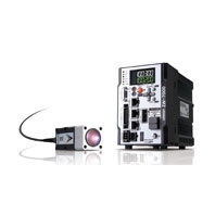
ZW-7000

Confocal Fiber Displacement Sensor

ZW-7000

Reliable measurements for any material and surface types

about this Product Family

Sensor Head

Item Specifications
ZW-S7010 ZW-S7020 ZW-S7030
Sensor controller ZW-7000T
Measurement center
distance
10 mm 20 mm 30 mm
Measuring range *1 ±0.5 mm ±1 mm ±2 mm
Static resolution *2 0.25 μm
Linearity *3 ±0.45 μm ±0.9 μm ±2.0 μm
Spot diameter
(Total measurent range) *4
50 μm dia. 70 μm dia. 100 μm dia.
Measurement cycle 20 μs to 400 μs
Operating ambient
illumination
Illumination on object surface max.30000: (incandescent light)
Ambient temperature
range
Operation: 0 to +50°C, Storage: -15 to +60°C
(No freezing and condensation)
Ambient humidity range Operation/storage: 35 or 85% (No condensation)
Degree of protection IP40 (IEC60529)
Vibration resistance
(destructive)
10 to 150 Hz (half amplitude 0.35 mm),
80 mins in each of X/Y/Z directions
Shock resistance
(destructive)
150 m/s2, 6 direction, 3 times each
(up/down, left/right, forward/backward)
Temperature
characteristic *5
0.6 μm/°C 1.1 μm/°C 1.8 μm/°C
LED Safety Risk Group 3 (IEC62471)
Material Chassis: aluminum die cast
Fiber cable sheath: PVC
Calibration ROM: PC
Fiber cable length 0.3 m, 2 m (flex-resistant cable)
Fiber cable minimum
bend radius
20 mm
Insulation resistance
(Calibration ROM)
Between case and all terminals: 20 MΩ (by 250 V megger)
Dielectric strength
(Calibration ROM)
Between case and all terminals: 1000 VAC, 50/60 Hz, 1 min
Weight Fiber cable length 0.3m Approx. 170g
Fiber cable length 2m Approx. 180g
Accessories Instruction Manual, 2 straps,
Calibration ROM fixing screws (M2), Note on Use

*1. The measurement range is based on 28 μs, or higher, measurement cycle.
*2. Capacity value when OMRON standard mirror surface target is measured at the measurement center distance as the average of 16,384 times
The value when the controller ZW-7000T is connected
*3. Material setting for the OMRON standard mirror surface target: Error from an ideal straight line when measuring on mirror surface.
*4. Capacity value defined by 1/e2 (13.5%) of the peak optical intensity of the measurement wavelength.
*5. Temperature characteristic at the measurement center distance when fastened with an aluminum jig between the Sensor Head and the target and the Sensor Head and the Sensor Controller are set in the same temperature environment.

Controller

Item Specifications
ZW-7000T
Input/output type NPN/PNP dual type
Number of connected sensor heads 1
Sensor head compatibility ZW-S70[][]
Light source for measurement White LED
LED Safety Risk Group 3 (IEC62471)
Segment
Display
Main display 11-segment white display, 6 digits
Sub-display 11-segment green display, 6 digits
LED display Status indicators HIGH (orange), PASS (green), LOW (orange), STABILITY (green), ZERO (green), ENABLE (green), THRESHOLD-H (orange), THRESHOLD-L (orange), RUN (green)
EtherCAT indicator ECAT RUN (green), L/A IN (Link/Activity IN) (green), L/A OUT (Link/Activity OUT) (green), ECAT ERR (red)
External I/F Ethernet 100BASE-TX/10BASE-T
EtherCAT EtherCAT exclusive protocol 100BASE-TX
RS-232C Max. 115,200 bps
Analog output
terminal block
Analog voltage output (OUT V) -10 V to +10 V, output impedance: 100 Ω
Analog current output (OUT A) 4 mA to 20 mA, max. load resistance: 300 Ω
32-pole
expansion
connector
Judgment output
(HIGH/PASS/LOW)
Transistor output system
Output voltage: 21.6 to 30 VDC
Load current: 50 mA or less
Residual voltage when turning ON: 1.2 V or less
Leakage voltage when turning OFF: 0.1 mA or less
Busy output
(BUSY)
Alarm output
(ALARM)
Enable output
(ENABLE 1)
Sync flag output
(SYNFLG)
Trigger busy output
(TRIGBUSY)
Logging state output
(LOGSTAT)
Logging error output
(LOGERR)
Stability output
(STABILITY)
Task state output
(TASKSTAT)
LIGHT OFF input
(LIGHT OFF 1)
DC input system
Input voltage: 24 VDC ± 10% (21.6 to 26.4 VDC)
Input current: 7 mA Type. (24 VDC)
ON voltage/ON current: 19 V/3 mA or less
ON voltage/ON current: 5 V/1 mA or less
Zero reset input
(ZERO 1)
Timing input
(TIMING 1)
Reset input
(RESET 1)
Sync input
(SYNC)
Trigger input
(TRIG)
Logging input
(LOGGING)
Bank Currently
selected
bank output
(BANK_OUT
1 to 3)
Transistor output system
Output voltage: 21.6 to 30 VDC
Load current: 50 mA or less
Residual voltage when turning ON: 2 V or less
Leakage voltage when turning OFF: 0.1 mA or less
Bank
Selection
input
(BANK_SEL
1 to 3)
DC input system
Input voltage: 24 VDC ± 10% (21.6 to 26.4 VDC)
Input current: 7 mA Type. (24 VDC)
ON voltage/ON current: 19 V/3 mA or more
OFF voltage/OFF current: 5 V/1 mA or less
Main
functions
Exposure time Automatic/Fixed
Measuring cycle 20 μs to 10 ms
Material setting Standard/Mirror/Rough surfaces
MEASUREMENT ITEM Height/Thickness of transparent object/Calculation
Filtering Median/Average/Differentiation/High pass/Low pass/Band pass
Output Scaling/Different holds/Zero reset/Logging for a measured value
Display Measured value/Threshold value/Analog output voltage or current value/Judgment result/Resolution/Exposure time/Internal logging condition/Peak amount of received light
Number of configurable banks Max. 8 banks
Task process Multi-task (up to 4 tasks per bank)
System Save/Initialization/Display measured information/Communication settings/Sensor head calibration/Key-lock/Zero reset memory/Timing input
Rating Power supply voltage 21.6 to 26.4 VDC (including ripple)
Current consumption 800 mA max.
Insulation resistance Across all lead wires and FG terminal: 20 MΩ (by 250 V megger)
Dielectric strength Between all lead wires and FG terminal: 500 VAC, 50/60 Hz, 1 minute
Environmental
resistance
Degree of protection IP20 (IEC60529)
Vibration resistance
(destructive)
10 to 55 Hz (half amplitude 0.35 mm), 50 mins in each of X/Y/Z directions
Shock resistance (destructive) 150 m/s2, 6 direction, 3 times each (up/down, left/right, forward/backward)
Ambient temperature range Operation: 0 to +40°C, Storage: -15 to +60°C
(No freezing and condensation)
Ambient humidity range Operation/storage: 35 to 85% (No condensation)
Grounding D-type grounding (grounding resistance of 100 Ω or less)
Note: For conventional Class D grounding
Material Chassis: PC
Weight Approx. 900g (main unit only), Approx. 150 g (Parallel cable)
Accessories Instruction Manual
Member registration sheet
Parallel cable (ZW-XCP2E)
10 Fiber cleaners (ZW-XCL)

Note:
Material setting for the OMRON standard mirror surface target: Error from an ideal straight line when measuring on mirror surface
The reference values for linearity when targets to measure are other than the above are as in the table below.

ZW Series EtherCAT Communications Specifications

Item Specification
Communications standard IEC61158 Type12
Physical layer 100BASE-TX(IEEE802.3)
Connectors RJ45 × 2
ECAT IN: EtherCAT input
ECAT OUT: EtherCAT output
Communications media Category 5 or higher (cable with double, aluminum tape and braided shielding) is recommended.
Communications distance Distance between nodes: 100 m max.
Process data Variable PDO mapping
Mailbox (CoE) Emergency messages, SDO requests, SDO responses, and SDO information
Distributed clock Synchronization in DC mode.
LED display L/A IN (Link/Activity IN) × 1, AL/A OUT (Link/Activity OUT) × 1, AECAT RUN × 1, AECAT ERR × 1

Automation Software Sysmac Studio

System Requirements *3

Item Requirement
Operating system (OS) *1 Windows XP (Service Pack 3 or higher, 32-bit version)/
Windows Vista (32-bit version)/
Windows 7 (32-bit/64-bit version)/
Windows 8 (32-bit/64-bit version)/
Windows 8.1 (32-bit/64-bit version)/
Windows 10(32-bit/64-bit version)
CPU Windows computers with Intel® Celeron® processor 540 (1.8 GHz) or faster CPU.
Intel® Core™ i5 M520 processor (2.4 GHz) or equivalent or faster recommended.
Main memory 2 GB min.
4 GB min. recommended
Hard disk Minimum 4.6 GB of Hard disk space is required to install.
Display XGA 1024 × 768, 16 million colors.
WXGA 1280 × 800 min. recommended
Disk drive DVD-ROM drive
Communications ports USB port corresponded to USB 2.0, or Ethernet port *2
Supported languages Japanese, English, German, French, Italian, Spanish, simplified Chinese, traditional Chinese, Korean

*1. Sysmac Studio Operating System Precaution: System requirements and hard disk space may vary with the system environment.
*2. Refer to the hardware manual for your Controller for hardware connection methods and cables to connect the computer and Controller.
*3. These system requirements and notes are for the Sysmac Studio Measurement Sensor Edition. Refer to the SYSMAC-SE2 Sysmac Studio Version 1 Operation Manual (Cat. No. W504) for system requirements and notes for the Standard Edition.

Version Information

ZW-7000 Series and Sysmac Studio
Use the latest version of Sysmac Studio Standard Edition/Measurement Sensor Edition.

ZW Series Version of ZW Series Corresponding version of
Sysmac Studio Standard Edition/
Measurement Sensor Edition
ZW-7000T Ver.2.01 Supported by version 1.15 or higher.