| Power supply voltage | A in model number: 100 to 240 VAC, 50/60 Hz
D in model number: 24 VAC, 50/60 Hz; 24 VDC |
|
|---|---|---|
| Operating voltage range | 85 to 110% of rated supply voltage | |
| Power consumption | 5.9 VA max. at 100 to 240 VAC, and 3.2 VA max. at 24 VAC or 1.8 W max. at 24 VDC | |
| Sensor input | Temperature input
Thermocouple: K, J, T, E, L, U, N, R, S, B, W, or PL II Platinum resistance thermometer: Pt100 or JPt100 Infrared temperature sensor (ES1B): 10 to 70°C, 60 to 120°C, 115 to 165°C, or 140 to 260°C Analog input Current input: 4 to 20 mA or 0 to 20 mA Voltage input: 1 to 5 V, 0 to 5 V, or 0 to 10 V |
|
| Input impedance | Current input: 150 Ω max., Voltage input: 1 MΩ min.
(Use a 1:1 connection when connecting the ES2-HB/THB.) |
|
| Control method | ON/OFF control or 2-PID control (with auto-tuning) | |
| Control
output |
Relay output | SPST-NO, 250 VAC, 2 A (resistive load), electrical life: 100,000 operations, minimum
applicable load: 5 V, 10 mA (reference value) |
| Voltage output
(for driving SSR) |
Output voltage 12 VDC ±20% (PNP), max. Load current: 21 mA, with short-circuit
protection circuit |
|
| Linear current
output |
4 to 20 mA DC/0 to 20 mA DC, load: 500 Ω max., resolution: Approx. 10,000 | |
| Auxiliary
output |
Number of outputs | 1 or 2 (depends on model) |
| Output
specifications |
SPST-NO relay outputs, 250 VAC, 2 A (resistive load),
Electrical life: 100,000 operations, Minimum applicable load: 10 mA at 5 V (reference value) |
|
| Event
input |
Number of inputs | 1 or 2 (depends on model) |
| External contact
input specifications |
Contact input ON: 1 kΩ max., OFF: 100 kΩ min. | |
| Non-contact input ON: Residual voltage 1.5 V max.; OFF: Leakage current 0.1 mA max. | ||
| Current flow: approx. 7 mA per contact | ||
| Setting method | Digital setting using front panel keys | |
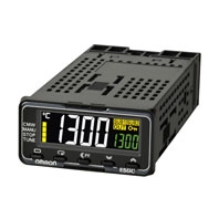
| Indication method | 11-segment digital displays and individual indicators
Character height: PV: 10.5 mm, SV: 5.0 mm |
|
| Multi SP | Up to eight set points (SP0 to SP7) can be saved and selected using the event inputs,
key operations, or serial communications. * |
|
| Bank switching | None | |
| Other functions | Manual output, heating/cooling control, loop burnout alarm, SP ramp, other alarm
functions, heater burnout (HB) alarm (including SSR failure (HS) alarm), 40% AT, 100% AT, MV limiter, input digital filter, self tuning, robust tuning, PV input shift, run/ stop, protection functions, extraction of square root, MV change rate limit, logic operations, temperature status display, simple programming, moving average of input value, display brightness setting, simple transfer output, and work bit message |
|
| Ambient operating
temperature |
-10 to 55°C (with no condensation or icing), For 3-year warranty: -10 to 50°C with
standard mounting (with no condensation or icing) |
|
| Ambient operating humidity | 25 to 85% | |
| Storage temperature | -25 to 65°C (with no condensation or icing) | |
| Altitude | 2,000 m max. | |
| Recommended fuse | T2A, 250 VAC, time-lag, low-breaking capacity | |
| Installation environment | Overvoltage category II, Pollution Degree 2 (EN/IEC/UL 61010-1) | |