Page top

Building Automation


Industrial Automation


Power Automation & Safety

Bangladesh Distributor

NX-PD / PF / PC / TBX

NX-series System Unit

NX-PD / PF / PC / TBX

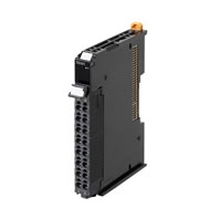
Power Supply Unit, Power Connection Unit, and FG Terminal Expansion Unit for NX-Series

about this Product Family

General Specification

Item Specification
Enclosure Mounted in a panel
Grounding method Ground to 100 Ω or less
Operating
environment
Ambient operating
temperature
0 to 55°C
Ambient operating
humidity
10% to 95% (with no condensation or icing)
Atmosphere Must be free from corrosive gases.
Ambient storage
temperature
-25 to 70°C (with no condensation or icing)
Altitude 2,000 m max.
Pollution degree 2 or less: Conforms to JIS B3502 and IEC 61131-2.
Noise immunity 2 kV on power supply line (Conforms to IEC61000-4-4.)
Overvoltage category Category II: Conforms to JIS B3502 and IEC 61131-2.
EMC immunity level Zone B
Vibration resistance Conforms to IEC 60068-2-6.
5 to 8.4 Hz with 3.5-mm amplitude, 8.4 to 150 Hz, acceleration of 9.8 m/s2,
100 min each in X, Y, and Z directions
(10 sweeps of 10 min each = 100 min total)
Shock resistance Conforms to IEC 60068-2-27. 147 m/s2, 3 times each in X, Y, and Z
directions
Applicable standards * cULus: Listed (UL508), ANSI/ISA 12.12.01, EU: EN 61131-2, C-Tick or RCM,
KC Registration, NK, and LR

* Refer to the OMRON website (www.ia.omron.com) or ask your OMRON representative for the most recent applicable standards for each model.

Specification

Additional NX Unit Power Supply Unit NX-PD1000

Unit name Additional NX Unit Power Supply Unit
Model NX-PD1000
External connection
terminals
Screwless push-in terminal block (8 terminals)
Power supply voltage 24 VDC (20.4 to 28.8 VDC)
NX Bus power supply
capacity
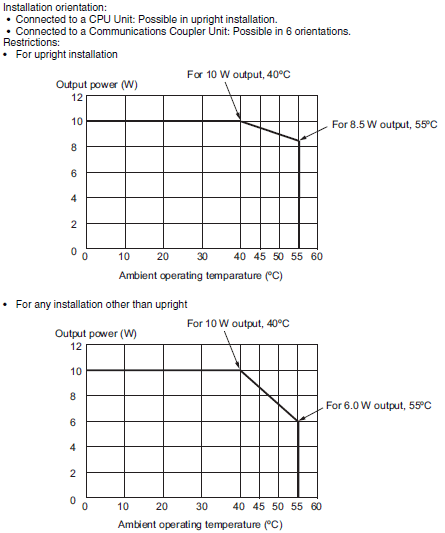
10 W max. (Refer to Installation orientation and restrictions for details.)
NX Unit power supply
efficiency
70%
Unwired terminal
current capacity
4 A max. (Including the current of through-wiring)
Dimensions 12 (W) × 100 (H) 71 × (D)
Isolation method No-isolation
Insulation resistance 20 MΩ min. between isolated circuits (at 100 VDC)
Dielectric strength 510 VAC between isolated circuits for 1 minute at a leakage current of 5 mA max.
NX Unit power
consumption
• Connected to a CPU Unit
0.85 W max.
• Connected to a Communications Coupler Unit
0.45 W max.
I/O current
consumption
No consumption
Weight 65g max.
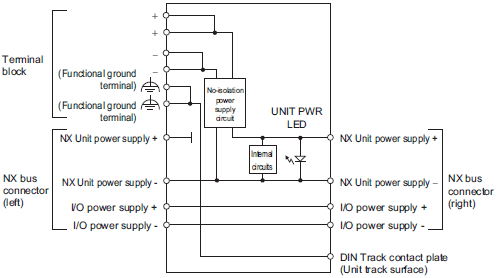
Circuit layout
3193_sp_2_1
Installation orientation
and restrictions
3193_sp_2_2
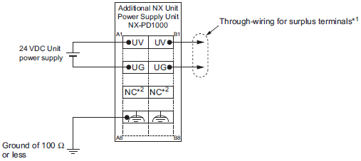
Terminal connection
diagram
3193_sp_2_3

*1. You can use the unwired terminals of the Unit power supply terminals (UV/UG) for through-wiring of the Additional NX
       Unit Power Supply Unit or the Unit power supply terminals on the EtherCAT Coupler Unit.
*2. The NC terminal is not connected to the internal circuit.

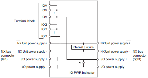
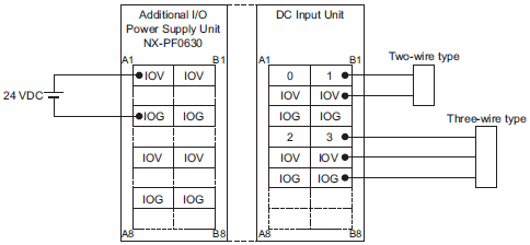
Additional I/O Power Supply Units NX-PF0[]30

Unit name Additional I/O Power Supply Unit
Model NX-PF0630 NX-PF0730
External connection
terminals
Screwless push-in terminal block (8 terminals)
Power supply voltage 5 to 24 VDC (4.5 to 28.8 VDC) *
I/O power supply
maximum current
4 A 10 A
Current capacity of I/O
power supply terminal
4 A max. 10 A max.
Dimensions 12 (W) × 100 (H) 71 × (D)
Isolation method No-isolation
Insulation resistance 20 MΩ min. between isolated circuits (at 100 VDC)
Dielectric strength 510 VAC between isolated circuits for 1 minute at a leakage current of 5 mA max.
NX Unit power
consumption
• Connected to a CPU Unit
0.85 W max.
• Connected to a Communications Coupler Unit
0.45 W max.
I/O current
consumption
10 mA max.
Weight 65 g max.
Circuit layout
3193_sp_3_1
Installation orientation
and restrictions
Installation orientation:
• Connected to a CPU Unit: Possible in upright installation.
• Connected to a Communications Coupler Unit: Possible in 6 orientations.
Restrictions: No restrictions
Terminal connection
diagram
3193_sp_3_2
Overload/low voltage
detection
Not supported
Protective function Not supported.

* Use an output voltage that is appropriate for the I/O circuits of the NX Units and the connected external devices.

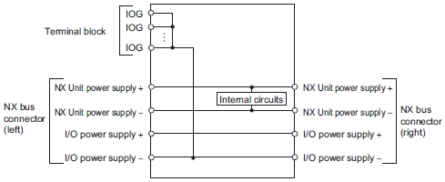
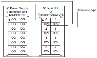
I/O Power Supply Connection Unit IOG terminal type NX-PC0010

Unit name I/O Power Supply Connection Unit
Model NX-PC0010
External connection
terminals
Screwless push-in terminal block (16 terminals)
Number of I/O power
supply terminals
IOG: 16 terminals
Current capacity of I/O
power supply terminal
4 A/terminal max.
Dimensions 12 (W) × 100 (H) 71 ×(D)
Isolation method No-isolation
Insulation resistance 20 MΩ min. between isolated circuits (at 100 VDC)
Dielectric strength 510 VAC between isolated circuits for 1 minute at a leakage current of 5 mA max.
NX Unit power
consumption
• Connected to a CPU Unit
0.85 W max.
• Connected to a Communications Coupler Unit
0.45 W max.
I/O current
consumption
No consumption
Weight 65 g max.
Circuit layout
3193_sp_4_1
Installation orientation
and restrictions
Installation orientation:
• Connected to a CPU Unit: Possible in upright installation.
• Connected to a Communications Coupler Unit: Possible in 6 orientations.
Restrictions: No restrictions
Terminal connection
diagram
3193_sp_4_2

I/O Power Supply Connection Unit IOV terminal type NX-PC0020

Unit name I/O Power Supply Connection Unit
Model NX-PC0020
External connection
terminals
Screwless push-in terminal block (16 terminals)
Number of I/O power
supply terminals
IOV: 16 terminals
Current capacity of I/O
power supply terminal
4 A/terminal max.
Dimensions 12 (W) × 100 (H) 71 × (D)
Isolation method No-isolation
Isolation resistance 20 MΩ min. between isolated circuits (at 100 VDC)
Dielectric strength 510 VAC between isolated circuits for 1 minute at a leakage current of 5 mA max.
NX Unit power
consumption
• Connected to a CPU Unit
0.85 W max.
• Connected to a Communications Coupler Unit
0.45 W max.
I/O current
consumption
No consumption
Weight 65 g max.
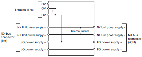
Circuit layout
3193_sp_5_1
Installation orientation
and restrictions
Installation orientation:
• Connected to a CPU Unit: Possible in upright installation.
• Connected to a Communications Coupler Unit: Possible in 6 orientations.
Restrictions: No restrictions
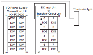
Terminal connection
diagram
3193_sp_5_2

I/O Power Supply Connection Unit IOV/IOG terminal type NX-PC00300

Unit name I/O Power Supply Connection Unit
Model NX-PC0030
External connection
terminals
Screwless push-in terminal block (16 terminals)
Number of I/O power
supply terminals
IOV: 8 terminals
IOG: 8 terminals
Current capacity of I/O
power supply terminal
4 A/terminal max.
Dimensions 12 (W) × 100 (H) 71 × (D)
Isolation method No-isolation
Insulation resistance 20 MΩ min. between isolated circuits (at 100 VDC)
Dielectric strength 510 VAC between isolated circuits for 1 minute at a leakage current of 5 mA max.
NX Unit power
consumption
• Connected to a CPU Unit
0.85 W max.
• Connected to a Communications Coupler Unit
0.45 W max.
I/O current
consumption
No consumption
Weight 65 g max.
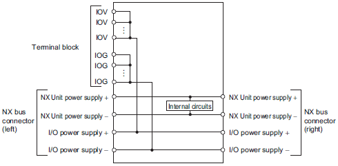
Circuit layout
3193_sp_6_1
Installation orientation
and restrictions
Installation orientation:
• Connected to a CPU Unit: Possible in upright installation.
• Connected to a Communications Coupler Unit: Possible in 6 orientations.
Restrictions: No restrictions
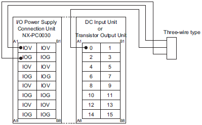
Terminal connection
diagram
3193_sp_6_2

Shield Connection Unit NX-TBX01

Unit name Shield Connection Unit
Model NX-TBX01
External connection
terminals
Screwless push-in terminal block (16 terminals)
Number of shield
terminals
14 terminals (The following two terminals are functional ground terminals.)
Dimensions 12 (W) × 100 (H) 71 × (D)
Isolation method Isolation between the SHLD functional ground terminal, and internal circuit: No-isolation
Insulation resistance 20 MΩ min. between isolated circuits (at 100 VDC)
Dielectric strength 510 VAC between isolated circuits for 1 minute at a leakage current of 5 mA max.
NX Unit power
consumption
• Connected to a CPU Unit
0.85 W max.
• Connected to a Communications Coupler Unit
0.45 W max.
I/O current
consumption
No consumption
Weight 65 g max.
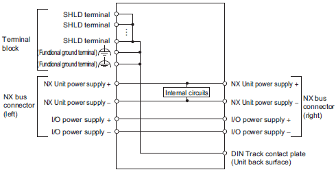
Circuit layout
3193_sp_7_1
Installation orientation
and restrictions
Installation orientation:
• Connected to a CPU Unit: Possible in upright installation.
• Connected to a Communications Coupler Unit: Possible in 6 orientations.
Restrictions: No restrictions
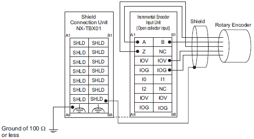
Terminal connection
diagram
3193_sp_7_2

Version Information

Connecting with CPU Units

Refer to the user's manual for the CPU Unit for the models of CPU Unit to which NX Units can be connected.

NX Unit Corresponding versions *
Model Unit Version CPU Unit Sysmac Studio
NX-PD1000 Ver.1.0 Ver.1.13 or later Ver.1.17 or higher
NX-PF0630
NX-PF0730
NX-PC0020
NX-PC0010
NX-PC0030
NX-TBX01

* Some Units do not have all of the versions given in the above table. If a Unit does not have the specified version, support is provided by the oldest available version after the specified version. Refer to the user's manuals for the specific Units for the relation between models and versions.

Connecting with Coupler Units

NX Unit Corresponding versions *
Model Unit
Version
EtherCAT Ethernet/IP
Communi-
cations
Coupler Unit
NJ/NX-series
CPU Units or
NY-series
Industrial PCs
Sysmac
Studio
Communi-
cations
Coupler Unit
Sysmac
Studio
NX-PD1000 Ver.1.0 Ver.1.0 or later Ver.1.05 or later Ver.1.06 or higher Ver.1.0 or later Ver.1.10 or higher
NX-PF0630
NX-PF0730 Ver.1.08 or higher
NX-PC0020 Ver.1.06 or higher
NX-PC0010
NX-PC0030
NX-TBX01

* Some Units do not have all of the versions given in the above table. If a Unit does not have the specified version, support is provided by the oldest available version after the specified version. Refer to the user’s manuals for the specific Units for the relation between models and versions.