Page top

Building Automation


Industrial Automation


Power Automation & Safety

Bangladesh Distributor

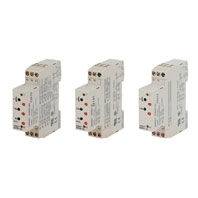
H3DS

Solid-state Timer

H3DS

DIN Track Mounted, Standard 17.5-mm Width Timer Range

about this Product Family

H3DS-M/-S/-A

General

Item H3DS-ML[] H3DS-SL[] H3DS-AL[]
Operating mode A: ON-delay (Signal or Power)
B: Flicker OFF start (Signal or Power)
B2: Flicker ON start (Signal or Power)
C: Signal ON/OFF-delay
D: Signal OFF-delay
E: Interval (Signal or Power)
G: Signal ON/OFF-delay
J: One-shot (Signal or Power)
A: ON-delay
B2: Flicker ON start
E: Interval
J: One-shot
A: ON-delay (fixed)
Input type Voltage input ---
Output type Relay: SPDT
External connections Screw terminal, Screw-Less Clamp
Terminal block Screw terminal type: Clamps two 2.5-mm2 max. bar terminals without sleeves.
Screw-Less Clamp type: Clamps two 1.5-mm2 max. bar terminals without sleeves.
Terminal screw
tightening torque
0.98 Nm max.
Mounting method DIN track mounting *
Attachment Nameplate label
Approved standards UL508, CSA C22.2 No.14
Conforms to EN61812-1, IEC60664-1 4 kV/2, VDE0106/P100
Output category according to IEC60947-5-1 (AC-13; 250 V 5 A/AC-14; 250 V 1 A/AC-15;
250 V 1 A/DC-13; 30 V 0.1 A/DC-14; 30 V 0.05 A)

* Can be mounted to 35-mm DIN Track with a plate thickness of 1 to 2.5 mm.

Time Ranges

Time scale display Time range
0.1 s 0.1 to 1.2 s
1 s 1 to 12 s
0.1 m 0.1 to 1.2 min
1 m 1 to 12 min
0.1 h 0.1 to 1.2 h
1 h 1 to 12 h
10 h 10 to 120 h

Note: When the time setting dial is set to "0" for any time scale, the output will operate instantaneously.

Ratings

Rated supply voltage *1, *2 24 to 230 VAC (50/60 Hz)/24 to 48 VDC
Operating voltage range 85% to 110% of rated supply voltage
Power reset Minimum power-off time: 0.1 s
Reset voltage 2.4 VAC/DC max.
Power consumption *3 AC:
32 VA max./3.0 W max. (typical: 30 VA/2.7 W) at 230 VAC
DC:
0.7 W max. (typical: 0.6 W) at 24 VDC
1.4 W max. (typical: 1.3 W) at 48 VDC
Voltage input Max. permissible capacitance between inputs lines (terminals B1 and A2): 2,000 pF
Load connectable in parallel with inputs (terminals B1 and A1).
H-level: 20.4 to 253 VAC/20.4 to 52.8 VDC
L-level: 0 to 2.4 VAC/DC
Control output Contact output:
5 A at 250 VAC with resistive load (cosφ = 1)
1 A at 250 VAC with inductive load (cosφ = 0.3)
5 A at 30 VDC with resistive load (cosφ = 1)
0.15 A max. at 125 VDC with resistive load,
0.1 A max. at 125 VDC with L/R of 7 ms.
The minimum applicable load is 10 mA at 5 VDC (P reference value).
Contact materials: Ag-alloy
Ambient temperature Operating: -10°C to 55°C (with no icing)
Storage: -25°C to 65°C (with no icing)
Ambient humidity Operating: 35% to 85%

*1. DC ripple rate: 20% max.
*2. Since an inrush current of 0.5 A will occur when using the power supply voltage at 24 VDC, pay careful attention
       when turning on or off the power supply to the Timer with a solid-state output such as a sensor.
*3. The power consumption is for mode A after the Timer counts the time-up time and for the AC input at 50 Hz. The
       power consumption of the H3DS-ML includes the input circuit with the B1 and A1 terminals short-circuited.

Characteristics

Accuracy of operating
time
±1% max. of FS (±1% ±10 ms max. at 1.2-s range)
Setting error ±10% ±50 ms max. of FS
Signal input time 50 ms min.
Influence of voltage ±0.7% max. of FS (±0.7% ±10 ms max. at 1.2-s range)
Influence of
temperature
±5% max. of FS (±5%±10 ms max. at 1.2-s range)
Insulation resistance 100 MΩ min. at 500 VDC
Dielectric strength Between current-carrying metal parts and exposed non-current-carrying metal parts: 2,000
VAC for 1 min.
Between control output terminals and operating circuit: 2,000 VAC for 1 min.
Between contacts not located next to each other: 1,000 VAC for 1 min.
Vibration resistance Malfunction: 0.5-mm single amplitude at 10 to 55 Hz
Destruction: 0.75-mm single amplitude at 10 to 55 Hz
Shock resistance Malfunction: 100 m/s2 3 times each in 6 directions
Destruction: 1,000 m/s2 3 times each in 6 directions
Impulse withstand
voltage
5 kV (between power terminals)
5 kV (between current-carrying metal parts and exposed non-current-carrying metal parts)
Noise immunity Square-wave noise generated by noise simulator (pulse width: 100 ns/1 μs, 1-ns rise)
±1.5 kV
Static immunity Malfunction: 4 kV
Destruction: 8 kV
Life expectancy Mechanical: 10 million operations min. (under no load at 1,800 operations/h)
Electrical: 100,000 operations min. (5 A at 250 VAC, resistive load at 360 operations/h) *
EMC (EMI) EN61812-1
Emission Enclosure: EN55011 Group 1 class B
Emission AC Mains: EN55011 Group 1 class B
Harmonic Current: EN61000-3-2
Voltage Fluctuation and Flickering: EN61000-3-3
(EMS) EN61812-1
Immunity ESD: IEC61000-4-2
Immunity RF-interference: IEC61000-4-3
Immunity Burst: IEC61000-4-4
Immunity Surge: IEC61000-4-5
Immunity Conducted Disturbance: IEC61000-4-6
Immunity Voltage Dip/Interruption: IEC61000-4-11
Case color Light gray (5Y7/1)
Degree of protection IP30 (Terminal block: IP20)
Weight Approx. 70 g

* For reference:
   In both cases, a life of 100,000 operations can be expected.

H3DS-F

General

Item H3DS-F
Operating mode Flicker-OFF/Flicker-ON start
Output type Relay: SPDT
External connections Screw terminal, Screw-Less Clamp
Terminal block Screw terminal type: Clamps two 2.5-mm2 max. bar terminals without sleeves.
Screw-Less Clamp type: Clamps two 1.5-mm2 max. bar terminals without sleeves.
Terminal screw
tightening torque
0.98 Nm max.
Mounting method DIN track mounting *
Attachment Nameplate label
Approved standards UL508, CSA C22.2 No.14
Conforms to EN61812-1, IEC60664-1 4 kV/2, VDE0106/P 100
Output category according to IEC60947-5-1 (AC-13; 250 V 5A/AC-15; 250 V 1 A/DC-13;
30 V 0.1 A)

* Can be mounted to 35-mm DIN Track with a plate thickness of 1 to 2.5 mm.

Time Ranges

Time scale display Time range
0.1 s 0.1 to 1.2 s
1 s 1 to 12 s
0.1 m 0.1 to 1.2 min
1 m 1 to 12 min
0.1 h 0.1 to 1.2 h
1 h 1 to 12 h

Note: When the time setting dial is set to “0” for any time scale, the output will operate instantaneously.

Ratings

Rated supply voltage * 24 to 230 VAC (50/60 Hz)/24 to 48 VDC
Operating voltage range 85% to 110% of rated supply voltage
Power reset Minimum power-off time: 0.1 s
Reset voltage 2.4 VAC/DC max.
Power consumption AC:
33 VA max./2.2 W max. (typical: 31 VA/2.0 W) at 230 VAC
DC:
0.7 W max. (typical: 0.6 W) at 24 VDC
1.4 W max. (typical: 1.2 W) at 48 VDC
Voltage input Max. permissible capacitance between inputs lines (terminals B1 and A2): 2,000 pF
Load connectable in parallel with inputs (terminals B1 and A1).
H-level: 20.4 to 253 VAC/20.4 to 52.8 VDC
L-level: 0 to 2.4 VAC/DC
Control output Contact output:
5 A at 250 VAC with resistive load (cosφ = 1)
1 A at 250 VAC with inductive load (cosφ = 0.3)
5 A at 30 VDC with resistive load (cosφ = 1)
Ambient temperature Operating: -10°C to 55°C (with no icing)
Storage: -25°C to 65°C (with no icing)
Ambient humidity Operating: 35% to 85%

* DC ripple rate: 20% max.

Characteristics

Accuracy of operating
time
±1% max. of FS (±1% ±10 ms max. at 1.2-s range)
Setting error ±10% ± 50 ms max. of FS
Influence of voltage ±0.5% max. of FS (±0.5% ±10 ms max. at 1.2-s range)
Influence of
temperature
±5% max. of FS (±5% ± 10 ms max. at 1.2-s range)
Insulation resistance 100 MΩ min. at 500 VDC
Dielectric strength Between current-carrying metal parts and exposed non-current-carrying metal parts: 2,000
VAC (50/60 Hz) for 1 min.
Between control output terminals and operating circuit: 2,000 VAC (50/60 Hz) for 1 min.
Between contacts not located next to each other: 1,000 VAC (50/60 Hz) for 1 min.
Impulse withstand
voltage
3 kV (between power supply terminals)
4.5 kV (between current-carrying metal parts and exposed non-current-carrying metal parts)
Noise immunity Square-wave noise generated by noise simulator (pulse width: 100 ns/1 μs, 1-ns rise)
±1.5 kV
Static immunity Malfunction: 4 kV
Destruction: 8 kV
Vibration resistance Malfunction: 0.5-mm single amplitude at 10 to 55 Hz
Destruction: 0.75-mm single amplitude at 10 to 55 Hz
Shock resistance Malfunction: 200 m/s2, 3 times each in 6 directions
Destruction: 300 m/s2, 3 times each in 6 directions
Life expectancy Mechanical: 10 million operations min. (under no load at 1,800 operations/h)
Electrical: 100,000 operations min. (5 A at 250 VAC, resistive load at 360 operations/h) *
EMC (EMI) EN61812-1
Emission Enclosure: EN55011 Group 1 class B
Emission AC Mains: EN55011 Group 1 class B
Harmonic Current: EN61000-3-2
Voltage Fluctuation and Flickering: EN61000-3-3
(EMS) EN61812-1
Immunity ESD: EN61000-4-2: 6 kV contact discharge (level 3), 8 kV air discharge (level 3)
Immunity RF-interference from AM Radio Waves: EN61000-4-3: 10 V/m (80 MHz to 1 GHz)
(level 3)
Immunity Burst: EN61000-4-4: 2 kV power port and output port (level 3), 1 kV control port
with capacitive clamp (level 3)
Immunity Surge: EN61000-4-5: 2 kV common mode (level 3), 1 kV differential mode (level 3)
Case color Light gray (5Y7/1)
Degree of protection IP30 (IP20 for terminal block)
Weight Approx. 70 g

* For reference:
   A maximum current of 0.15 A can be switched at 125 VDC (cosφ=1).
   A maximum current of 0.1 A can be switched if L/R is 7 ms.
   In both cases, a life of 100,000 operations can be expected.
   The minimum applicable load is 10 mA at 5 VDC (failure level: P).

H3DS-G

General

Item H3DS-G
Operating mode Star-delta operation
Operating/Reset method Time-limit operation/Self-reset
External connections Screw terminal, Screw-Less Clamp
Terminal block Screw terminal type: Clamps two 2.5-mm2 max. bar terminals without sleeves.
Screw-Less Clamp type: Clamps two 1.5-mm2 max. bar terminals without sleeves.
Terminal screw tightening
torque
0.98 Nm max.
Output type (Star operation circuit) Relay: SPST-NO
(Delta operation circuit) Relay: SPST-NO
Mounting method DIN track mounting *
Attachment Nameplate label
Approved standards UL508, CSA C22.2 No.14
Conforms to EN61812-1, IEC60664-1 4 kV/2, VDE0106/P100
Output category according to IEC60947-5-1 (AC-13; 250 V 5A/AC-15; 250 V 1 A/
DC-13; 30 V 0.1 A)

* Can be mounted to 35-mm DIN Track with a plate thickness of 1 to 2.5 mm.

Time Ranges

Time scale Star operation time ranges
x 1 1 to 12 s
x 10 10 to 120 s

Star-delta transfer time Programmable at 0.05 s, 0.1 s, 0.5 s, or 1 s

Ratings

Rated supply voltage * 24 to 230 VAC (50/60 Hz)/24 to 48 VDC
Operating voltage range 85% to 110% of rated supply voltage
Power reset Minimum power-off time: 0.5 s
Reset voltage 2.4 VAC/DC max.
Power consumption AC:
21 VA max./1.7 W max. (typical: 20 VA/1.6 W) at 230 VAC
DC:
1.3 W max. (typical: 1.2 W) at 24 VDC
0.7 W max. (typical: 0.6 W) at 48 VDC
Control output Contact output:
5 A at 250 VAC with resistive load (cosφ = 1)
1 A at 250 VAC with inductive load (cosφ = 0.3)
5 A at 30 VDC with resistive load (cosφ = 1)
Ambient temperature Operating: -10°C to 55°C (with no icing)
Storage: -25°C to 65°C (with no icing)
Ambient humidity Operating: 35% to 85%

* DC ripple rate: 20% max.

Characteristics

Accuracy of operating
time
±1% max. of FS
Setting error ±10% ± 50 ms max. of FS
Total tolerance of
transfer time
± (25% FS + 5 ms) max.
Influence of voltage ±0.5% max. of FS
Influence of
temperature
±5% max. of FS
Insulation resistance 100 MΩ min. at 500 VDC
Dielectric strength Between current-carrying metal parts and exposed non-current-carrying metal parts: 2,000
VAC (50/60 Hz) for 1 min.
Between control output terminals and operating circuit: 2,000 VAC (50/60 Hz) for 1 min.
Between contacts not located next to each other: 1,000 VAC (50/60 Hz) for 1 min.
Impulse withstand
voltage
3 kV (between power supply terminals)
4.5 kV (between current-carrying metal parts and exposed non-current-carrying metal parts)
Noise immunity Square-wave noise generated by noise simulator (pulse width: 100 ns/1 μs, 1-ns rise)
±1.5 kV
Static immunity Malfunction: 4 kV
Destruction: 8 kV
Vibration resistance Malfunction: 0.5-mm single amplitude at 10 to 55 Hz
Destruction: 0.75-mm single amplitude at 10 to 55 Hz
Shock resistance Malfunction: 200 m/s2, 3 times each in 6 directions
Destruction: 300 m/s2, 3 times each in 6 directions
Life expectancy Mechanical: 10 million operations min. (under no load at 1,800 operations/h)
Electrical: 100,000 operations min. (5 A at 250 VAC, resistive load at 360 operations/h) *
EMC (EMI) EN61812-1
Emission Enclosure: EN55011 Group 1 class B
Emission AC Mains: EN55011 Group 1 class B
Harmonic Current: EN61000-3-2
Voltage Fluctuation and Flickering: EN61000-3-3
(EMS) EN61812-1
Immunity ESD: EN61000-4-2: 6 kV contact discharge (level 3), 8 kV air discharge (level 3)
Immunity RF-interference from AM Radio Waves: EN61000-4-3: 10 V/m (80 MHz to 1 GHz)
(level 3)
Immunity Burst: EN61000-4-4: 2 kV power port and output port (level 3), 1 kV control port
with capacitive clamp (level 3)
Immunity Surge: EN61000-4-5: 2 kV common mode (level 3), 1 kV differential mode (level 3)
Case color Light gray (5Y7/1)
Degree of protection IP30 (IP20 for terminal block)
Weight Approx. 70 g

* For reference:
   A maximum current of 0.15 A can be switched at 125 VDC (cosφ=1).
   A maximum current of 0.1 A can be switched if L/R is 7 ms.
   In both cases, a life of 100,000 operations can be expected.
   The minimum applicable load is 10 mA at 5 VDC (failure level: P).

H3DS-X

General

Item H3DS-X
Operating mode ON-delay
Operating/Reset method Time-limit operation/self-resetting
Output type SCR output
External connections Screw terminal, Screw-Less Clamp
Terminal block Screw terminal type: Clamps two 2.5-mm2 max. bar terminals without sleeves.
Screw-Less Clamp type: Clamps two 1.5-mm2 max. bar terminals without sleeves.
Terminal screw tightening
torque
0.98 Nm max.
Mounting method DIN track mounting *
Attachment Nameplate label
Approved standards UL508, CSA C22.2 No.14
Conforms to EN61812-1, IEC60664-1 4 kV/2, VDE0106/P100

* Can be mounted to 35-mm DIN Track with a plate thickness of 1 to 2.5 mm.

Time Ranges

Time scale display Time range
0.1 s 0.1 to 1.2 s
1 s 1 to 12 s
0.1 m 0.1 to 1.2 min
1 m 1 to 12 min
0.1 h 0.1 to 1.2 h
1 h 1 to 12 h
10 h 10 to 120 h

Note: When the time setting dial is set to “0” for any time scale, the output will operate instantaneously.

Ratings

Rated supply voltage * 24 to 230 VAC/VDC (50/60 Hz)
Operating voltage range 85% to 110% of rated supply voltage
Power reset Minimum power-off time: 0.1 s
Reset voltage 1.0 VAC/VDC max.
Reset current 5 mA max.
Power consumption 5 mA max.
Control output SCR output: 5 mA to 0.7 A
Ambient temperature Operating: -10°C to 55°C (with no icing)
Storage: -25°C to 65°C (with no icing)
Ambient humidity Operating: 35% to 85%

* The ripple in DC power supply must be 5% max.

Characteristics

Accuracy of operating
time
±1% max. of FS (±1% ±10 ms max. at 1.2-s range)
Setting error ±10% ± 50 ms max. of FS
Reset time 0.1 s max.
Influence of voltage ±0.5% max. of FS (±0.5%±10 ms max. at 1.2-s range)
Influence of
temperature
±5% max. of FS (±5%±10 ms max. at 1.2-s range)
Insulation resistance 100 MΩ min. at 500 VDC
Dielectric strength Between current-carrying metal parts and exposed non-current-carrying metal parts: 2,000
VAC for 1 min
Impulse withstand
voltage
3 kV (between power supply terminals)
4.5 kV (between current-carrying metal parts and exposed non-current-carrying metal parts)
Noise immunity Square-wave noise generated by noise simulator (pulse width: 100 ns/1 μs, 1-ns rise)
±1.5 kV (between power supply terminals)
Static immunity Malfunction: 4 kV
Destruction: 8 kV
Vibration resistance Malfunction: 0.5-mm single amplitude at 10 to 55 Hz
Destruction: 0.75-mm single amplitude at 10 to 55 Hz
Shock resistance Malfunction: 200 m/s2, 3 times each in 6 directions
Destruction: 300 m/s2, 3 times each in 6 directions
EMC (EMI) EN61812-1
Emission Enclosure: EN55011 Group 1 class B
Emission AC Mains: EN55011 Group 1 class B
Harmonic Current: EN61000-3-2
Voltage Fluctuation and Flickering: EN61000-3-3
(EMS) EN61812-1
Immunity ESD: EN61000-4-2: 6 kV contact discharge (level 3), 8 kV air discharge (level 3)
Immunity RF-interference from AM Radio Waves: EN61000-4-3: 10 V/m (80 MHz to 1 GHz)
(level 3)
Immunity Burst: EN61000-4-4: 2 kV power port and output port (level 3), 1 kV control port
with capacitive clamp (level 3)
Immunity Surge: EN61000-4-5: 2 kV common mode (level 3), 1 kV differential mode (level 3)
Case color Light gray (5Y7/1)
Degree of protection IP30 (IP20 for terminal block)
Weight Approx. 70 g