Page top

Building Automation


Industrial Automation


Power Automation & Safety

Bangladesh Distributor

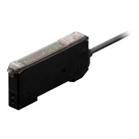
E3X-DAC-S

Color Sensing Digital Fiber Amplifier Unit

E3X-DAC-S

Easy and Reliable. The Fiber Amplifier Unit That Sees in Color

about this Product Family

Fiber Amplifier Units

Type Standard models Advanced models with
simultaneous
2-color determination
Advanced models with
4-color determination
Model E3X-DAC[]-S[]
([]: 11/41/6/8)
E3X-DAC[]-S[]
([]: 21/51)
E3X-DAC[]B-S[]
([]: 21/51)
Sensing distance Depends on the Fiber Unit. Refer to below for details.
Sensing object Reflective models: Standard 11 color cards *1, Through-beam models: Opaque or
translucent object
Light source (wavelength) White LED (420 to 700 nm)
Sensing method C Mode: RGB ratio determination (or I Mode: Light intensity determination for red,
green, or blue;
Black Mode: Determination of total light intensity for red, green, and blue) *2
Number of
registered colors
1 2 (simultaneous
determination)
4 (2-color simultaneous
determination × 2 banks)
Power supply voltage 12 to 24 VDC ±10%, ripple (p-p) 10% max.
Power consumption 960 mW max. (current consumption: 40 mA max. at power supply voltage of 24 VDC)
Control outputs NPN or PNP open collector
Load power supply voltage: 26.4 VDC max.
Load current: 50 mA max. (residual voltage: 2 V max.)
Number of control outputs 1 2
External input *3 --- Remote control Bank switching
Protection circuits Reverse polarity for power supply connection, Output short-circuit, Reversed
output polarity protection
Response
time
Super-high-speed
mode *4
Operate or reset: 60 μs Operate or reset: 120 μs
High-speed mode Operate or reset: 300 μs Operate or reset: 600 μs
Standard mode Operate or reset: 1 ms Operate or reset: 2 ms
High-resolution
mode
Operate or reset: 4 ms Operate or reset: 8 ms
Sensitivity setting (color
registration, allowable range)
Teaching (one-point teaching or teaching with/without workpiece) or manual
adjustment
Functions Operation mode ON for match (ON for same color as registered color) or ON for mismatch (ON for
different color from registered color)
Timer function Timer type: OFF delay, ON delay, or one-short, Timer time: 1 ms to 5 s (variable)
Control outputs --- Output for each channel, AND output, and OR output
Remote control --- One-point teaching,
teaching with/without
workpiece, zero reset, and
light emission OFF
Bank switching
(switching between banks A
and B and banks C and D)
Display switch *5 Seven patterns total: Match + Threshold, Margin + Threshold, Analog bar display,
Peak + Bottom, etc.
Initialization Initial reset (factory defaults) or user reset (saved
settings)
Initial reset (factory
defaults)
Zero reset Supported Not supported
Indicators Operation indicator
(orange)/I mode display
indicator (orange)
Operation indicator for each channel (orange)
Digital display 7-segment displays (Main display: Red, Sub-display: Green)
Display direction Switchable between normal and reversed.
Ambient illumination (Receiver
side)
Incandescent lamp: 3,000 lux
Sunlight: 10,000 lux
Ambient temperature range *6 Operating: -25°C to 55°C, Storage: -30°C to 70°C (with no icing or condensation)
Ambient humidity range Operating and storage: 35% to 85% (with no condensation)
Insulation resistance 20 MΩ min. (at 500 VDC)
Dielectric strength 1,000 VAC at 50/60 Hz for 1 minute
Vibration resistance Destruction: 10 to 50 Hz with a 1.5-mm double amplitude for 2 h each in X, Y and Z
directions
Shock resistance Destruction: 500 m/s2, for 3 times each in X, Y and Z directions
Degree of protection IEC IP50 (with Protective Cover attached)
Connection method Pre-wired (standard cable
length: 2 m) or reduced-
wiring connector
(Units connected: 16 max.)
Pre-wired (standard cable length: 2 m)
Weight (packed state) Pre-wired model: Approx. 100 g, Amplifier unit connector model: Approx. 55 g
Materials Case Polybutylene terephthalate (PBT)
Cover Polycarbonate (PC)
Accessories Instruction manual

*1. Sensing Object: Standard Color Card (230 Colors) from Japan Color Enterprise Co., Ltd.)

Color (11 standard colors) Munsell color notation
White N9.5
Red 4R 4.5/12.0
Yellow/red 4YR 6.0/11.5
Yellow 5Y 8.5/11.0
Yellow/green 3GY 6.5/10.0
Green 3G 6.5/9.0
Blue/green 5BG 4.5/10.0
Blue 3PB 5.0/10.0
Blue/purple 9PB 5.0/10.0
Purple 7P 5.0/10.0
Red/purple 6RP 4.5/12.5
(Black) (N2.0)
*2.When teaching with/without a workpiece, the best sensing method will be automatically selected (RGB ratio (C Mode)
     or light intensity determination (I Mode)). If color differences are not strong enough and RGB ratios would result in
     unstable detection, then light intensity determination (I Mode) will be selected. The detection mode can be set to C,
     I, or Black Mode.

*3. Input Specifications

Contact input
(relay or switch)
Non-contact input
(transistor)
NPN ON: Shorted to 0 V (sourcing current: 1 mA max.).
OFF: Open or shorted to Vcc.
ON: 1.5 V max. (sourcing current: 1 mA max.)
OFF: Vcc - 1.5 V to Vcc (leakage current: 0.1 mA max.)
PNP ON: Shorted to Vcc (sinking current: 3 mA max.).
OFF: Open or shorted to 0 V.
ON: Vcc - 1.5 V to Vcc (sinking current: 3 mA max.)
OFF: 1.5 V max. (leakage current: 0.1 mA max.)
       Refer to the Instruction Manual for the external input pulse width.
       A pulse width of 300 ms or longer is required to switch banks for the E3X-DAC[]B-S.
*4.Mutual interference prevention cannot be used in super-high-speed mode, and light intensity determination (I Mode)
      must be used. The response time will be 150 μs if an AND or OR is set for the control outputs.
*5. With light intensity determination (I Mode and Black Mode), the correlation is not displayed, but rather the light
      intensity is displayed.
*6. The allowable ambient operating temperature changes according to the number of Units that are linked. 2 Units:
      −25 to 55°C, 3 to 10 Units: −25 to 50°C, and 11 to 16 Units: −25 to 45°C

Amplifier Unit Connectors

Model E3X-CN11 E3X-CN12
Rated current 2.5 A
Rated voltage 50 V
Contact resistance 20 mΩ max. (20 mVDC max., 100 mA max.)
(The figure is for connection to the Fiber Amplifier Unit and the adjacent Connector. It does
not include the conductor resistance of the cable.)
No. of insertions Destruction: 50 times (The figure for the number of insertions is for connection to the Fiber
Amplifier Unit and the adjacent Connector.)
Materials Housing Polybutylene terephthalate (PBT)
Contacts Phosphor bronze/gold-plated nickel
Weight (packed state) Approx. 55 g Approx. 25 g

Sensing Distance

(Unit: mm)

Reflective Models

Sensing object White paper Standard color card (11 colors)
(mutual determination)
Type High-
resolu-
tion
mode
Stan-
dard
mode
High-
speed
mode
Super-
high-
speed
mode
High-
resolu-
tion
mode
Stan-
dard
mode
High-
speed
mode
Super-
high-
speed
mode
Standard
models
General-
purpose
E32-DC200 70 54 46 18 14 10 8.5 6
E32-D11R/
E32-D12R/
E32-D15XR/
E32-D11N/
E32-DC200BR(B4R)
42 32 26 11 8.5 6 5 3.5
E32-D14LR 11 8.5 7 2.5 2.4 1.7 1.4 1
E32-D15YR/
E32-D15ZR
10 7.5 6.5 2.5 2.1 1.5 1.3 0.9
E32-D211/
E32-DC200E/
E32-D22/
E32-D25X/
E32-DC200F(F4)
20 16 14 5 4.5 3 2.5 1.5
E32-D24 8.8 6.7 5.8 2.1 1.8 1.3 1.1 0.7
E32-D25Y/
E32-D25Z
5.8 4.5 3.8 1.4 1.2 0.9 0.7 0.5
Break-
resistant
E32-D11/
E32-D15XB
42 32 26 11 8.5 6 5 3.5
E32-D21B/
E32-D221B
19 15 13 4.5 4.1 3 2.4 1.5
E32-D21/
E32-D22B
8.8 6.7 5.8 2.1 1.8 1.3 1.1 0.7
E32-D25XB 14 10 9 3 3 2.1 1.7 1.1
Fluorine
coating
E32-D11U 42 32 26 11 8.5 6 5 3.5
Special-
beam
models
Long
distance,
high
power
E32-A09 20 to
38
24 to
36
26 to
32
--- 20 to
38
24 to
36
26 to
32
---
E32-D11L 90 70 60 22 19 13 11 7.5
E32-D21L/
E32-D22L
35 26 22 8 7 5 4 2.5
Coaxial E32-CC200 60 45 35 16 12 9 7 4
E32-CC200R/
E32-C11N
35 26 22 9 7.5 5 4.5 3
E32-D32L 35 26 22 9 7.5 5 4.5 3
E32-C31/E32-D32 17 13 11 4.5 3.7 2.7 2.2 1.5
E32-C31N 7.7 6 4.8 2.1 1.6 1.2 0.9 0.7
Area
sensing
E32-D36P1 35 26 22 9 7.5 5 4.5 3
Environ-
ment
resistive
models
Heat-
resistant
E32-D51 55 42 36 14 11 8.5 7 4.5
E32-D81R-S/
E32-D61-S
20 15 13 5 4 3 2.5 1.5
E32-D73-S 13 10 8.5 3.5 2.8 2 1.7 1.2
Chemical
resistant
E32-D12F 22 17 15 6 4.9 3.5 2.9 2
E32-D14F 9 7 6 2 2.1 1.4 1.2 0.6

Through-beam Models

Sensing object Opaque object Translucent object *
Type High-
resolu-
tion
mode
Stan-
dard
mode
High-
speed
mode
Super-
high-
speed
mode
High-
resolu-
tion
mode
Stan-
dard
mode
High-
speed
mode
Super-
high-
speed
mode
Standard
models
General-
purpose
E32-TC200 200 160 140 70 45 32 26 22
E32-T11R/E32-T12R/
E32-T15XR/
E32-T11N/
E32-TC200BR(B4R)
150 110 95 50 30 22 18 16
E32-T14LR/
E32-T15YR/
E32-T15ZR
55 44 38 19 12 8.5 7 6.5
E32-TC200E/
E32-T22/E32-T222/
E32-T25X/
E32-TC200F(F4)
80 60 50 46 17 12 10 7
E32-T24/E32-T25Y/
E32-T25Z
48 36 32 26 10 7 6 4
Break-
resistant
E32-T11/E32-T12B/
E32-T15XB
190 140 120 60 40 28 24 20
E32-T21/E32-T221B/
E32-T22B
70 55 48 40 15 11 9 6
E32-T25XB 55 42 36 30 11 8 7 4.5
Fluorine
coating
E32-T11U 190 140 120 60 40 28 24 20
Special-
beam
models
Long
distance,
high
power
E32-T17L 4300 3200 2800 1400 900 600 500 460
E32-TC200 + E39-F1 1100 850 700 360 220 160 140 120
E32-T11R + E39-F1 1000 750 650 340 220 150 130 110
E32-T11N + E39-F1 1000 750 650 320 200 150 120 110
E32-T11 + E39-F1 1000 750 650 320 200 150 120 110
E32-T14 950 700 600 300 200 140 120 100
E32-T11L/E32-T12L 350 250 200 120 75 55 46 40
E32-T11L + E39-F2 220 160 140 75 46 32 28 25
E32-T11R + E39-F2 110 85 70 36 22 16 14 12
E32-T11 + E39-F2 180 140 120 60 38 28 22 20
E32-T12L/E32-T22L 160 120 100 90 34 24 20 14
Fine
beam
E32-T22S 500 400 350 170 110 80 65 55
E32-T24S 360 280 240 120 75 55 46 40
Area
sensing
E32-T16 750 600 500 250 160 110 95 85
E32-T16PR 240 180 150 80 50 36 30 26
E32-T16JR 200 160 130 65 44 30 26 22
E32-T16WR 360 280 240 120 75 55 46 40
Label
detection
(Slot
Sensor)
E32-G14 10 10
Environ-
ment
resistive
models
Heat-
resistant
E32-T51 200 160 140 70 44 32 26 22
E32-T54 60 48 42 20 13 9.5 8.1 7
E32-T81R-S 75 60 50 26 16 11 9.5 8.5
E32-T61-S 120 95 80 42 26 19 16 14
E32-T61-S + E39-F1 950 700 600 320 200 140 120 100
E32-T61-S + E39-F2 120 95 80 42 26 19 16 14
E32-T84S-S 360 280 240 120 75 55 46 40
Chemical
resistant
E32-T11F 550 420 360 180 110 80 70 60
E32-T12F 850 650 550 280 180 120 100 95
E32-T14F 100 80 70 35 22 16 13 12
E32-T51F 380 300 250 130 80 55 48 44
E32-T81F-S 190 150 120 65 40 28 24 22
Vacuum
resistant
E32-T51V 55 42 36 18 11 8.5 7 6
E32-T51V + E39-F1V 280 200 180 90 55 42 35 30
E32-T54V 36 28 24 12 7.5 5.5 4.5 4
E32-T54V + E39-F1V 140 100 90 46 28 20 17 15
E32-T84SV 130 100 85 45 28 20 17 15
*These sensing distances are recommended to make the most of the detection capabilities of the Sensor.