|
Supply voltage *2 |
CE marking | 100 to 240 VAC, 50/60 Hz | 24 VAC, 50/60 Hz; 24 VDC |
|---|---|---|---|
| UL certification | 100 to 120 VAC, 50/60 Hz | ||
| Operating voltage range | 85% to 110% of rated supply voltage | ||
| Power consumption | 22 VA max. (with maximum load) | 15 VA/10 W max. (with maximum load) | |
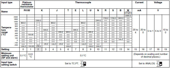
| Sensor input *3 | Thermocouple: K, J, T, E, L, U, N, R, S, B, W Platinum resistance thermometer: Pt100 Current input: 4 to 20 mA DC, 0 to 20 mA DC (including remote SP input) Voltage input: 1 to 5 VDC, 0 to 5 VDC, 0 to 10 VDC (including remote SP input) (Input impedance: 150 Ω for current input, approx. 1 MΩ for voltage input) |
||
|
Control output |
Voltage (pulse) output |
12 VDC, 40 mA max. with short-circuit protection circuit (E5AR-TQQE3MW-FLK: 21 mA max.) | |
| Current output | 0 to 20 mA DC, 4 to 20 mA DC; load: 500 Ω max. (including transfer output) (Resolution: Approx. 54,000 for 0 to 20 mA DC; Approx. 43,000 for 4 to 20 mA DC) |
||
| Relay output | Position-proportional control type (open, closed) N.O., 250 VAC, 1 A (including inrush current) |
||
| Auxiliary output | Relay Output N.O., 250 VAC, 1 A (resistive load) Transistor Output Maximum load voltage: 30 VDC; Maximum load current: 50 mA; Residual voltage: 1.5 V max.; Leakage current: 0.4 mA max. |
||
| Potentiometer input | 100 Ω to 2.5 kΩ | ||
| Event input | Contact | Input ON: 1 kΩ max.; OFF: 100 kΩ min. | |
| No-contact | Input ON: Residual voltage of 1.5 V max.; OFF: Leakage current of 0.1 mA max. | ||
| Event input | Short-circuit: Approx. 4 mA | ||
| Remote SP input | Refer to the information on sensor input. | ||
| Transfer output | Refer to the information on control output. | ||
| Control method | 2-PID or ON/OFF control | ||
| Setting method | Digital setting using front panel keys or setting using serial communications | ||
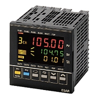
| Indication method | 7-segment digital display and single-lighting indicator Character Height PV display: 12.8 mm; SV display: 7.7 mm; MV display: 7.7 mm |
||
| Other functions | Depends on model. | ||
| Ambient operating temperature | -10 to 55°C (with no icing or condensation) For 3 years of assured use: -10 to 50°C (with no icing or condensation) |
||
| Ambient operating humidity | 25% to 85% | ||
| Storage temperature | -25 to 65°C (with no icing or condensation) | ||