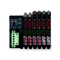
| Item | Description | |
|---|---|---|
| Communications Method | Sets parameters using Explicit messages | |
|
Communications functions |
Remote I/O Communications Slave function |
Edits slave device parameters, enables device monitor functions |
|
Message Communications function |
E3X-MC11-SV2 can be connected | |
| Configurator | DeviceNet communications | |
| Mobile Console connection | Monitors ON/OFF output, status, incident light level (digital display data) | |
| Power supply | Supplied from the DeviceNet communications connector (power is also supplied to all connected Sensors through Wire-reducing Connectors) |
|
| Maximum connectable Sensors *1 | For remote I/O communications 1-CH mode *2: 13 For remote I/O communications 2-CH mode *3 or for remote I/O communications 2-CH mode + detection level monitoring mode *4: 16 |
|
| Connectable Sensors *5 | E3X-DA-S Series or E3X-MDA Series Digital Fiber Sensor E3C-LDA Series Laser Photoelectric Sensor with Separate Digital Amplifier E2C-EDA High-resolution Digital Proximity Sensor with Separate Amplifier (use connector-type Amplifier Units and the E3X-CN02 Cordless Slave Connector) |
|
| Power supply voltage | 11 to 25 VDC | |
| Current consumption *6 | 70 mA max. | |
| Ambient operating temperature | -20 to 55°C | |
| Ambient operating humidity | 30% to 85% (with no condensation) | |
| Storage temperature | -30 to 70°C | |
| Dimensions (mm) | 30 x 34.6 x 71.3 (W x H x D) | |
| Weight (packed state) | Approx. 150 g | |


