Page top

Building Automation


Industrial Automation


Power Automation & Safety

Bangladesh Distributor

K8AC-H

Digital Heater Element Burnout Detector

K8AC-H

A high-precision Heater Element Burnout Detector compatible with a wide-range of heater control methods.

about this Product Family

Ratings

Heater control method Models for ON/OFF control
(e.g., SSRs or contactors)
Models for phase control and cyclic control
Model K8AC-H[][]C[]-FLK K8AC-H[][]P[]-FLK
Power supply voltage 100 to 240 VAC (50/60 Hz) *2
Operating voltage range 85% to 110% min. of the rated power supply voltage (85 to 264 V)
Power consumption (at max. load) 35 VA max.
Applicable circuits Single-phase or three-phase (with same model)
Applicable control methods ON/OFF control (e.g., temperature controller with relay output)
SSR control (e.g., temperature controller with voltage output)
Cyclic control and phase control (e.g., temperature controller with current output)
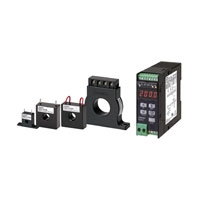
Input signal and applicable Current
Transformer
Current measurement via two special Current Transformers (Burnout alarm set value can be set
separately for each Current Transformer.)
Refer to Current Measurement Ranges by Model on Data Sheet for information on the current
measurement range and applicable Current Transformer.
Measurement method Average value calculation
Gate input
signal *1
ON/OFF control Voltage = 12/24 VDC (continuous input possible to
30 VDC)
Input impedance = 4 kΩ min.
---
SSR control ON voltage: 9.6 VDC max., OFF voltage: 1 VDC min.
Minimum voltage pulse ON time for burnout
detection: 200 ms min.
Input impedance = 4 kΩ min.
---
Cyclic and phase
control
--- 4 to 20 mA DC (Burnout detection is possible for
an input of 7 mA or greater.)
Input impedance = 50 Ω max.
Outputs Relay contact
outputs:
K8AC-H[][][]C-FLK
One SPDT relay contact output
Same output used for heater burnout, SSR short circuit, SSR open circuit, and heater layer short
circuit alarms.
0.3 A at 125 VAC (resistive load), 1 A at 30 VDC (resistive load)
Maximum switching capacity: 37.5 VA, 30 W
Mechanical durability: 50 million operations min., electrical durability: 100,000 operations min.
Transistor outputs
(NPN open-
collector):
K8AC-H1[][]T-FLK
Two transistor outputs (NPN open-collector)
One ALM output: Outputs heater burnout alarm or heater layer short circuit alarm.
One SSR error output: Outputs SSR short circuit alarm or SSR open circuit alarm.
12 to 24 VDC, 50 mA max.
OFF leakage current: 100 μA max., ON residual voltage: 1.5 V max.
Transistor outputs:
K8AC-H2[][]N-FLK
Two transistor outputs: Can be used either NPN open-collector outputs or PNP equivalent outputs.
One ALM output: Outputs heater burnout alarm or heater layer short circuit alarm.
One SSR error output: Outputs SSR short circuit or SSR open circuit detection.
12 to 24 VDC, 50 mA
OFF leakage current: 100 μ A max., ON residual voltage: 1.5 V max.
Communications RS-485 1200, 2400, 4800, 9600, 19200 bps (CompoWay/F)
Indication method 7-segment digital display: No. of display digits: 4 (red)
LED status indicators: RUN (green), ADJ (orange), SET (orange), GATE (orange), SSR (orange) and
ALM (orange)
Main functions Heater burnout alarm, heater layer short circuit alarm, SSR short circuit detection, SSR open circuit
detection, voltage fluctuation compensation, output ON-delay timer, energy-saving mode, key
protection, and power supply voltage measurement
Ambient
temperature
Operating - 10 to 55 ° C (with no icing or condensation)
Storage - 25 to 65 ° C (with no icing or condensation)
Ambient
humidity
Operating 25% to 85% (with no condensation)
Storage 25% to 85% (with no condensation)
Altitude 2,000 m max.
Accessories Instruction sheet
Case material PC (Polycarbonate)
Case color N1.5 (clear black)
Mounting method Mounting to a DIN Track

*1. The gate input enables correct measurement by syncing to heater control.
      When using it with ON/OFF control, receive the relay contact output from the temperature controller or other controller
      with a 24-VDC auxiliary relay and then use this signal as the gate input signal to the K8AC.
      The gate function can also be disabled. If it is disabled, the gate input can be used as a normal undercurrent/
      overcurrent relay.
*2. When using the K8AC-H for a 380 to 480-V AC power supply circuit, use a step-down transformer. Contact your
      OMRON representative for information on transformers.
*3. Order the Current Transformers separately.

Characteristics

Heater control method Models for ON/OFF control
(e.g., SSRs or contactors)
Models for phase control and cycle control
Model K8AC-H[][][]C[]-FLK K8AC-H[][]P[]-FLK
Heater
current input
(at 10 to
30°C)
category II
Input range K8AC-H[]1[][]: 0.200 to 2.200 A (Current Transformer: K8AC-CT20S (5.8 dia.), K8AC-CT20L (12 dia.) *1)
K8AC-H[]2[][]: 2.00 to 22.00 A (Current Transformer: K8AC-CT20S (5.8 dia.), K8AC-CT20L (12 dia.) *1)
K8AC-H[]3[][]: 20.0 to 200.0 A (Current Transformer: K8AC-CT200 (12 dia.), K8AC-CT200L (30 dia.) *1)
Measurement
accuracy
± 3% rdg ± 10 digits max. *2 ± 6% rdg ± 10 digits max. (at control level of 100%) *2
Voltage
fluctuation
compensation
category II
Input range 85 to 264 VAC
Measurement
accuracy
± 3% rdg ± 10 digits max.
Gate input Input range 0 to12 VDC or 0 to 24 VDC
ON: 9.6 VDC max., OFF: 1 VDC min.
4 to 20 mA DC
Display cycle Selectable: Immediate, 0.2 s, 0.5 s, 1.0 s
Output ON-delay time 0.0 to 99.9 s (operating time)
Soft start time 0.0 to 99.9 s (used when using the soft start function of a Power Controller)
Output reset method Automatic reset
Alarm hysteresis 1 to 999 digits
Output response time 500 ms max. 3.5 s max.
Insulation resistance 20 MΩ min.
Between terminals and case
Between power supply terminals/CT primary terminals and gate input terminals/communications terminals
Between power supply terminals/CT primary terminals and output terminals
Between gate input terminal/communications terminals and output terminals
Dielectric strength 2,000 V for 1 min
Between terminals and case
Between power supply terminals/CT primary terminals and gate input terminals/communications terminals
Between power supply terminals/CT primary terminals and output terminals
Between gate input terminal/communications terminals and output terminals
Noise immunity Power supply terminals normal/common mode: ±1,500 V (startup 1-ns square-wave noise, pulse width:
1 μs/100 ns)
Vibration resistance Vibration: 10 to 55 Hz, Acceleration: 50 m/s2 for 5 min with 10 sweeps each in X, Y, and Z directions
Shock resistance 150 m/s2 (100 m/s2 for relay contacts) 3 times in 6 directions in X, Y, and Z directions
Maximum
allowable
input
Current
Transformer
primary
current
K8AC-H[]1[][]: 4 A: 30 s, 12 A: 1 s
K8AC-H[]2[][]: 40 A: 30 s, 120 A: 1 s
K8AC-H[]3[][]: 400 A: 30 s, 1,200 A: 1 s
Gate signal:
4 to 20 mA
40 mA DC continuous
Voltage pulse
gate input
30 VDC continuous
Input
impedance
Gate signal:
4 to 20 m
50 Ω max.
Voltage pulse
gate input
4 kΩ min.
Weight Approx. 200 g
Memory protection Non-volatile memory (number of writes: 100,000 operations)
Installation environment Installation Category 2, Pollution Class 2
Approved standards UL61010-1 and CAN/CSA C22.2 No.61010-1-04 (UL pending)
EN 61010-1 (IEC 61010-1) (TÜV evaluation)
EMC EMI: EN61326-1 Industrial electromagnetic environment
Radiated Interference Electromagnetic Field Strength: EN55011 Group 1, class A
Noise Terminal Voltage: EN55011 Group 1, class A
EMS: EN61326-1 Industrial electromagnetic environment
ESD Immunity: EN61000-4-2: 4 kV (contact discharge), 8 kV (air discharge)
Electromagnetic Immunity: EN61000-4-3: 10 V/m 1 kHz sine wave amplitude modulation (80 MHz to 1 GHz)
Fast Transient Burst Immunity: EN61000-4-4: 2 kV (power line), 1 kV (I/O signal line)
Surge immunity: EN61000-4-5: 1 kV (line to line, power line), 2 kV (line to ground, power line)
Conducted Noise Immunity EN61000-4-6: 3 V (0.15 to 80 MHz)
Voltage Dip/Interrupting Immunity EN61000-4-11: 0.5 cycle, 0.180 °, 100% (rated voltage)

Note: For phase control, the accuracy is the value when the control value of the power regulator is 100% (when the
         waveform of the heater current is a sine wave). "rdg" is the error in the reading of the input current.
*1. The Current Transformers are sold separately.
*2. The values for measurement current apply when the K8AC-H is used in combination with a Current Transformer.

Current Measurement Ranges by Model

Model K8AC-H[]1[][]-FLK K8AC-H[]2[][]-FLK K8AC-H[]3[][]-FLK
Current measurement range 0.200 to 2.200 A AC 2.00 to 22.00 A AC 20.0 to 200.0 A AC
Current Transformer K8AC-CT20S: 5.8-mm through-hole diameter
or
K8AC-CT20L: 12-mm through-hole diameter
K8AC-CT200:
12-mm through-hole diameter
or
K8AC-CT200L:
30-mm through-hole diameter

I/O Ratings

Relay Contact Output

Load Resistive load (cosΦ = 1)
Rated load 125 VAC, 0.3 A, 30 VDC, 1 A
Maximum contact voltage 125 VAC, 60 VDC
Maximum contact current 1 A
Maximum switching capacity 37.5 VA, 30 W
Minimum applicable load
(failure rate P value, reference value)
5 VDC, 10 mA
Mechanical life expectancy 50,000,000 operations min. (at a switching frequency of 18,000 times/h)
Electrical life expectancy
(Ambient temperature condition: 20°C)
100,000 operations min. (at rated load and switching frequency of 1,800 times/h)

Transistor Output

Maximum load voltage 12 to 24 VDC (+10%, -15%)
Maximum load current 50 mA
OFF leakage current 100 μ A max.
ON residual voltage 1.5 V max.

Communications Specifications

Communications RS-485
Transmission method Two-wire, half-duplex
Synchronization method Start-stop synchronization
Baud rate 1,200, 2,400, 4,800, 9,600, or 19,200 bps
Transmission code ASCII