Page top

Building Automation


Industrial Automation


Power Automation & Safety

Bangladesh Distributor

A3P

Lighted Pushbutton Switches

A3P

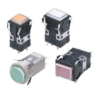
Large Rectangular-bodied Lighted Pushbutton Switches

about this Product Family

Ratings

Contact Ratings

Silver Alloy Contacts (for Standard Loads)

Rated voltage (V) Non-inductive load (A) Inductive load (A)
Resistive load Lamp load Inductive load Motor load
NC NO NC NO NC NO NC NO
125 VAC
250 VAC
5
3
0.7
0.5
3
2
1.3
0.8
8 VDC
14 VDC
30 VDC
125 VDC
250 VDC
5
5
4
0.4
0.2
2
2
2
0.05
0.03
4
4
3
0.4
0.2
3
3
3
0.05
0.03

Note: 1. The above values are for steady-state currents.
           2. Inductive load: Power factor = 0.4; time constant = 7 ms.
           3. The lamp load has an inrush current of 10 times the steady-state current.
           4. The motor load has an inrush current of 6 times the steady-state current.
Standard testing condition
(1) Ambient temperature: 20 ± 2°C
(2) Ambient humidity: 65 ± 5%RH
(3) Operating frequency: 20 times/min.

Gold Alloy Contacts (for Microloads)

Rated voltage (V) 0.1 A at 30 VDC (resistive load);
0.1 A at 125 VAC (resistive load)
Minimum applicable load 1 mA at 5 VDC

LED and Incandescent Lamp Ratings

LED for LED-lighted Models

Model A3PJ/M2PJ A3PA/M2PA
Rated current Rated current
Applied voltage Rated voltage Single screen 2-split screen Single screen 2-split screen
5 VDC ±5% 5 VDC 80 mA --- 80 mA ---
12 VDC ±5% 12 VDC 40 mA --- 40 mA ---
24 VDC ±5% 24 VDC 20 mA 15 mA × 2 20 mA 13 mA × 2

LED for Chameleon Models

Applied voltage Rated voltage Rated current
Green Red
12 VDC ± 5% 12 VDC 26 mA 20 mA
24 VDC ± 5% 24 VDC 13 mA 10 mA

Incandescent Lamp

Item Standard lamp Low-power lamp
Applied voltage Rated voltage Rated current Model Rated current Model
5 VDC 6 V 200 mA SLL-06 100 mA SLL-06H
12 VDC 14 V 80 mA SLL-14 40 mA SLL-14H
24 VDC 28 V 40 mA SLL-28 25 mA SLL-28H

LED Lamp (for LED Lamp-lighted Models)

Type Applied voltage Rated voltage Rated current Model
DC only 5 VDC ± 5% 5 VDC 30 mA SLL-05E[]
12 VDC ± 5% 12 VDC 15 mA SLL-12E[]
24 VDC ± 5% 24 VDC 12.5 mA SLL-24E[]

Characteristics

Operating frequency Mechanical 120 operations/minute max. *1
Electrical 30 operations/minute max.
Insulation resistance 100 MΩ min. (at 500 VDC)
Contact
resistance
Standard load 40 mΩ max. (initial value)
Microload 40 mΩ max. (initial value)
Dielectric strength Between terminals of
same polarity
1,000 VAC, 50/60 Hz for 1 minute *2
Between terminals of
different polarity
2,000 VAC, 50/60 Hz for 1 minute
Between current-carrying
metal part and ground
2,000 VAC, 50/60 Hz for 1 minute
Between each terminal
and non-current-carrying
metal part
2,000 VAC, 50/60 Hz for 1 minute
Between lamp terminals 1,000 VAC, 50/60 Hz for 1 minute *3
Vibration resistance Malfunction 10 to 55 Hz, 1.5 mm double amplitude (1 ms max.)
Shock resistance Destruction 500 m/s2 max.
Malfunction 200 m/s2 max. (1 ms max.)
Life expectancy Mechanical Momentary operation models: 1,000,000 operations min.
Alternate operation models: 200,000 operations min.
(One operation consists of set and reset operations.)
Electrical 100,000 operations min.
Weight Approx. 30 g
Inrush current NC Silver contact: 10 A max.
NO Silver contact: 10 A max.
Ambient operating temperature LED-lighted models: -10°C to 40°C (with no icing or condensation)
Incandescent lamp-lighted models: -10°C to 50°C (with no icing or condensation)
Ambient operating humidity 35% to 85%RH
Ambient storage temperature -25°C to 65°C
Degree of protection IP40
Electric shock protection class Class II
PTI (proof tracking index) 175
Pollution degree 3 (IEC947-5-1)

*1. With alternate operation models, 60 operations/minute max. One operation cycle consists of set and reset operations.
*2. 600 VAC for microloads.
*3. With no incandescent lamp or LED lamp mounted.

Operating Characteristics

Model A3PJ series A3PA series A3PT series
Operating Characteristics Momentary operation models Alternate operation models Momentary operation models Alternate operation models Momentary operation models Alternate operation models
Operating force OF max. 5.88 N 6.86 N 5.88 N 6.86 N 3.92 N 4.90 N
Releasing force RF min. 0.39 N 0.29 N 0.39 N 0.29 N 0.39 N 0.29 N
Total travel TT Approx.
3.5 mm
Approx.
3.5 mm
Approx.
3.5 mm
Approx.
3.5 mm
Approx.
3.5 mm
Approx.
3.5 mm
Pretravel PT max. 3 mm 3 mm 3 mm 3 mm 3 mm 3 mm
Lock travel alternate LTA min. --- 0.5 mm --- 0.5 mm --- 0.5 mm