Building Automation
Industrial Automation
Power Automation & Safety


Bangladesh Distributor
H5CX-A-N
Digital Timer

Image
Digital Timer, 48×48×84 mm, 100 to 240 VAC
| Rated supply voltage |
100 to 240 VAC 50/60 Hz |
|---|---|
| Time range |
0.001s to 9999h |
| Input method |
No-voltage/Voltage input (Switchable) |
| Output modes |
A (Signal ON delay1) A-1 (Signal ON delay2) A-2 (Power ON delay1) A-3 (Power ON delay2) b (Repeat cycle1) b-1 (Repeat cycle2) d (Signal OFF delay) E (Interval) F (Cumulative) Z (ON/OFF-duty adjustable flicker) S (Stopwatch) toff (Flicker OFF start1) ton (Flicker ON start1) toff-1 (Flicker OFF start2) ton-1 (Flicker ON start2) |
| Control output |
SPDT |
| Display method |
7-segment negative transmissive LCD |
| Character height |
Present value: 12 mm (Red, green or orange programmable) Equipped Set value: 6 mm (Green) |
| External connection method |
Screw terminals |
- Ratings/Performance
As of August 8, 2016
| Rated supply voltage | 100 to 240 VAC 50/60 Hz |
|---|---|
| Operating voltage range | 85% to 110% of rated supply voltage |
| Power consumption | Approx. 6.2VA |
| Time ranges(Number of ranges) | 10 |
| Time ranges | 0.001 s to 9.999 s / 0.01 s to 99.99 s / 0.1 s to 999.9 s / 1 s to 9999 s / 0.1 min to 999.9 min / 1 min to 9999 min / 0.1 h to 999.9 h / 1 h to 9999 h 1sec~99min59sec |
| Select method | Dip switch or Operation Key |
| Input signals | Signal, Gate, Reset |
| Input method | No-voltage/Voltage input (Switchable) |
| No-voltage input(Solid state input) | ON impedance: 1 kOhm max. Leakage current: Approx. 12 mA ON residual voltage: 3 V max. OFF impedance: 100 kOhm min. (The DC voltage must be 30 VDC max.) |
| No-voltage input(Contact input) | Use contact which can adequately switch 5 mA at 10 V (The DC voltage must be 30 VDC max.) |
| No-voltage input(Applicable two-wire sensor) | Leakage current: 1.5 mA max. Switching capacity: 5 mA min. Residual voltage3.0 VDC max. Operating voltage: 10 VDC |
| Voltage input | High level: 4.5 to 30 VDC Low level: 0 to 2 VDC Input resistance: 4.7 kOhm (The DC voltage must be 30 VDC max.) |
| Minimum input signal width | 1 ms/ 20 ms (Switchable)(Signal, Reset, Gate) |
| Standby time | 250 ms max. (Control output is turned OFF and no input is accepted during sensor waiting time.) |
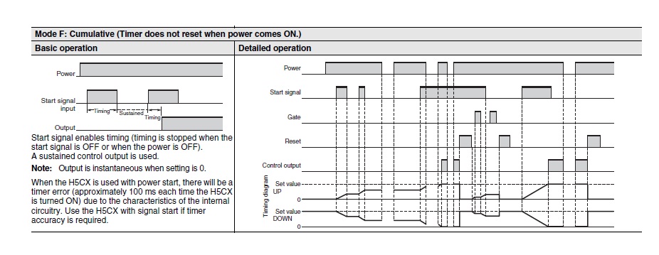
| Output modes | A (Signal ON delay1) A-1 (Signal ON delay2) A-2 (Power ON delay1) A-3 (Power ON delay2) b (Repeat cycle1) b-1 (Repeat cycle2) d (Signal OFF delay) E (Interval) F (Cumulative) Z (ON/OFF-duty adjustable flicker) S (Stopwatch) toff (Flicker OFF start1) ton (Flicker ON start1) toff-1 (Flicker OFF start2) ton-1 (Flicker ON start2) |
| Control output (Contact output) | Type: SPDT Switching capacities (Resistive load): 5 A at 250 VAC/30 VDC Minimum applicable load: 10 mA at 5 VDC (failure level: P) |
| One-shot output time | 0.01 to 99.99 s |
| Reset system | Power reset(A,A-1,A-2,b,d,E,Z,S,ton,toff mode) / Automatic reset(A-1,b,b-1,d,E,Z,ton,toff,S,ton-1,toff-1 mode) / External reset / Manual reset |
| Power reset | Minimum power-opening time: 0.5 s (except for A-3, b-1, F, ton-1 and toff-1 mode) |
| Timer mode | Elapsed time (UP) and remaining time (DOWN) (selectable) |
| Display method | 7-segment negative transmissive LCD |
| Digit | 4 digit |
| Character height | Present value: 12 mm (Red, green or orange programmable) Equipped Set value: 6 mm (Green) |
| Key protect method | Key protect Switch |
| Memory backup method | EEP-ROM Number of rewite: 100000 times min. / Service life: 10 years min. |
| Ambient temperature | Operating: -10 to 55 ℃ When mount timer side by side: -10 to 50 CEL Storag: -25 to 70 ℃ (with no icing or condensation) |
| Ambient humidity | Operating: 25 to 85%RH Storag: 25 to 85%RH |
| Total accuracy | Accuracy of operating time and setting error (including temperature and voltage influences) Power-ON start: +/- 0.01% +/- 50 ms max. The values are based on the set value. Accuracy of operating time and setting error (including temperature and voltage influences) Signal start: +/- 0.005% +/- 30 ms max. The values are based on the set value. |
| Insulation resistance | 100 MΩ min. (at 500 VDC) between current carrying metal parts and exposed non-current carrying metal parts / between non-continuous contacts |
| Dielectric strength | between current-carrying metal parts and non-curernt-carrying metal parts: 2000 between operating power circuit and input circuit: 2000 between input and control output and operation power circuit: 2000 between non-continuous contacts: 1000 |
| Impulse withstand voltage | between power terminals: 5 kV between current-carrying terminals and exposed non-curernt-carrying metal parts: 5 kV |
| Noise immunity | Between power terminals: +/- 1.5 kV Between input terminals: +/- 600 V Square-wave noise by noise simulator (Pulse width: 100 ns/1 us, Rise: 1-ns) |
| Static immunity | Mulfunction: 8 kV ,Destruction: 15 kV |
| Vibration resistance (Destruction) | 10 to 55 Hz, 0.75 mm single amplitude in each 3 directions for 2 hours |
| Vibration resistance (Malfunction) | 10 to 55 Hz 0.35 mm single amplitude in each 3 directions for 10 min |
| Shock resistance (Destruction) | 300 m/s**2, in each 6 directions (3 axes) 3 times |
| Shock resistance (Malfunction) | 100 m/s**2, in each 6 directions (3 axes) 3 times |
| Mechanical life | 10000000 operations min. (under no load at 1800 operations/h) |
| Electrical life | 100000 operations min. (5 A at 250 VAC resistive load at 1800 operations/h) |
| Degree of protection | Panel surface: IEC IP66, UL508 Type 4X (indoors) (when using the Y92S-29 Waterproof Packing and Y92F-30 Flush Mounting Adapter) / Case rear: IP40 / Terminal block: IP20 |
| Mounting method | Flush mounting |
| External connection method | Screw terminals |
| Case color | Black (Munsell N1.5) (The front part can be changed to light gray or white in sold separately panel) |
| Attachment | Flush mounting adapter Waterproof rubber packing Label for DIP switch settings Shock Prevention Cover |
| Accessory (sold separately) | Y92A-48F1: Soft Cover Y92A-48: Hard Cover Y92F-30: Flush Mounting Adapter Y92F-45: Flush Mounting Adapter Y92S-29: Waterproof Packing Y92P-CXT4S: Replacement Front Panel Y92P-CXT4G: Replacement Front Panel Y92P-CXT4B: Replacement Front Panel |
| Weight | 約115g |
As of August 8, 2016
- Dimensions
As of August 8, 2016
As of August 8, 2016
- Terminal arrangement
As of August 8, 2016

As of August 8, 2016
- Input connections
As of August 8, 2016

As of August 8, 2016
- Operating chart
As of August 8, 2016
As of August 8, 2016
- Electrical life
As of August 8, 2016
As of August 8, 2016

about this Product