 Cautions
-
 Relays
-
 General Purpose Relays
-
 Solid-state Relays
- Power Controllers
-
Power Controllers
|
|
|
|
| Safety Precautions |
Safety Precautions for All Power Controllers
Refer to the Safety Precautions for individual products for precaution specific to each product.

Do not touch the Power Controller or the heat sink while the power is being supplied or immediately after the power supply has been turned OFF. Touching the Power Controller or heat sink while it is hot may result in burns.

Do not touch the Power Controller LOAD terminals immediately after the power has been turned OFF. Shock may result due to the electrical charge stored in the builtin snubber circuit.

Always attach the cover terminal if the Power Controller has one. Contact with current-carrying parts may result in shock.

Always turn OFF the power supply before performing wiring. Not doing so may result in shock.

Do not allow short-circuit current to flow to the load side of the Power Controller. The Power Controller may explode if short-circuit current flows.

Precautions for Safe Use
OMRON constantly strives to improve quality and reliability. Power Controllers, however, use semiconductors, and semiconductors may commonly malfunction or fail. In particular, it may not be possible to ensure safety if the Power Controllers are used outside the rated ranges. Therefore, always use the Power Controllers within the ratings. When using a Power Controller, always design the system to ensure safety and prevent human accidents, fires, and social harm in the event of Power Controller failure. System design must include measures such as system redundancy, measures to prevent fires from spreading, and designs to prevent malfunction.
1. Do not apply voltage or current in excess of the ratings to the terminals of the Power Controller. Doing so may result in failure or burn damage.
2. Do not use the Power Controller with loose terminal screws. Doing so may result in burn damage due to abnormal heat produced by the terminals.
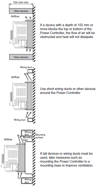
3. Do not block the movement of the air surrounding the Power Controller or heat sink. Abnormal heating of the Power Controller may result in shorting failures of the elements or burn damage.
4. Follow the Precautions for Correct Use when performing wiring or tightening the screws. If the Power Controller is used with the wiring or screw tightening performed improperly, burn damage may occur due to abnormal heat generated when the power is being applied.
Precautions for Correct Use
Load
The primary side of a transformer can be connected as the load provided that the magnetic flux density of the transformer is 1.25 T or less.
Installation Precaution
The 60-A G3PW weighs approximately 2 kg. Injury may result if the G3PW falls during installation. Handle it with care.
Mounting Procedure
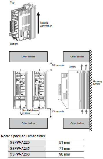
For cooling efficiency, install the Power Controller in the correct direction. If you mount the G3PW in any direction other than the direction that is shown in the following figure, product failure or accidents may occur. Installing the Power Controller in the wrong direction may cause it to malfunction or to be damaged.

Mounting Position in Relation to Wiring Duct

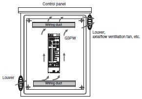
Control Panel Ventilation
When mounting the Power Controller in a control panel, consider measures such as installing louvers or fans for ventilation in the control panel.
If the air intake and outlet ports have filters, perform periodic maintenance to prevent the filters from becoming clogged.
Install devices in such a way that airflow is not blocked inside or outside of the air intake and outlet ports.
If using a heat exchanger for cooling inside the panel, it is most effective to mount it on the front of the Power Controller.

Wiring
Make sure that the lead wires are thick enough according to the current.
Be sure to turn off power to the G3PW when wiring. The G3PW has current leakage although the G3PW is turned off if the power supply is connected to the G3PW, which may give an electric shock.
Do not wire power lines or high-tension lines along with the lines of the G3PW in the same conduit, otherwise the G3PW may be damaged or malfunction due to induction. Be sure to wire the lines of the G3PW separated from power lines or high-tension lines or laid in an exclusive, shielded conduit.
Tightening Torque
Load Terminals
When connecting to the load terminals, use the specified wire size for each model of Power Controller.
| Model | Recommended wire size | Tightening torque | Terminal screws |
| G3PW-A220 | AWG 10 to 18 | 1.8 N·m | M4 |
| G3PW-A245 | AWG 6 * | 2.8 N·m | M5 |
| G3PW-A260 |
* Crimp terminals that conform to UL and CSA specifications must be used.
Command Input and Power Supply Terminals
| Model | Recommended wire size | Tightening torque | Terminal screws |
| All models | AWG 14 to 18 | 0.8 to 1.0 N·m | M3.5 |
Control Terminals
| Model | Recommended wire size | Tightening torque | Terminal screws (See note.) |
| All models | AWG 16 to 26 | 0.22 N·m | M2 |
* Only models with terminal blocks with small slotted screws have terminal screws.
Use copper AWG26 to AWG16 twisted-pair cable when connecting the wires directly.
Strip the wire sheathing for the following lengths, according to the connector type.
• Small slotted terminals: 7 mm
• Screwless clamp terminals: 9 mm
When using twisted wires, it is recommended that you attach a ferrule with an insulating cover that conforms to DIN 46228-4 and connect the ferrule to the terminal.
Use shielded twisted-pair wires for RS-485 communications wires. A maximum of 500 m total of wiring can be used.
Wiring for Error Detection
If a contactor is employed and operated with the relay output signal of the G3PW for error detection, make sure that the G3PW is closer to the power supply than the contactor.
However, if you shut off only the load terminals (L1 and T1) with a breaker or contactor, there will still be a voltage at the load terminals if a voltage is applied to the power supply terminals (terminals 4 and 5). Always shut OFF the voltage to the power supply terminals whenever you perform wiring work.
Instruments
| Instrument | Remarks |
| Thermal type | Available |
| Digital type displaying root-mean-square values | |
| Moving-iron type | |
| Rectifier type | Not available (not precise enough) |
| Multimeter | |
| Digital multimeter |
Note: Use a meter that displays the effective values of the AC circuit voltage and current.
Operation Monitoring
You can check the operating status on the seven-segment display.
Variable Resistors
Use the following variable resistor for the main external setting and the external duty setting.
G32X-V2K (2 kΩ)


