 Cautions
-
 Switches
-
 Level Switches
-
 Basic Switches
-
 Limit Switches
- Push Buttons / Indicator Lamps
-
 Thumbwheel Switches
-
Push Buttons / Indicator Lamps
|
|
|
|
| Safety Precautions |
Safety Precautions for All Pushbutton Switches/Indicators
For the individual precautions for a Switch, refer to the Safety Precautions in the section for that Switch.

Do not perform wiring with power supplied to the Switch. Do not touch the terminals or other charged parts of the Switch while power is being supplied. Doing so may result in electric shock.


Do not apply a voltage between the incandescent lamp and the terminal that is greater than the rated voltage. Doing so may damage the lamp or LED and cause the Operation Unit to pop out.

Always turn OFF the power and wait for 10 minutes before replacing the incandescent lamp. If the lamp is replaced immediately after the power is turned OFF, the remaining heat may cause burns.

Precautions for Correct Use
Electrical Characteristics
1. Operating Load
The switching load capacity of the Switch greatly varies between AC and DC. Always be sure to apply the rated load. The control capacity will drastically drop if it is a DC load. This is because a DC load has no current zero-cross point, unlike an AC load. Therefore, if an arc is generated, it may continue for a comparatively long time. Furthermore, the current direction is always the same, which results in a contact relocation phenomena whereby the contacts easily stick to each other and do not separate when the surfaces of the contacts are uneven.
Some types of load have a great difference between normal current and inrush current. Make sure that the inrush current is within the permissible value. The greater the inrush current in the closed circuit is, the greater the contact abrasion or shift will be. Consequently, contact weld, contact separation failures, or insulation failures may result. Furthermore, the Switch may be broken or damaged.
If the load is inductive, counter-electromotive voltage will be generated. The higher the voltage is, the higher the generated energy will be, which will increase the abrasion of the contacts and contact relocation phenomena. Be sure to use the Switch within the rated conditions.
Inrush Current
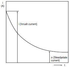
Approximate control capacities are given in ratings tables, but these alone are insufficient to guarantee correct operation. For special types of load, with unusual switching voltage or current waveforms, test whether correct operation is possible with the actual load before application.
When switching for microloads (voltage or current), use a Switch with microload specifications. The reliability of silver-plated contacts, which are used in Switches for standard loads, will be insufficient for microloads.
When switching microloads or very high loads that are beyond the switching capacity of the Switch, connect a relay suitable for the load.
Type of Load vs. Inrush Current
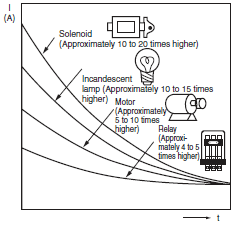
All the performance ratings given are for operation under the following conditions unless otherwise specified.
Inductive load: A minimum power factor of 0.4 (AC) and a maximum time constant of 7 ms (DC)
Lamp load: An inrush current 10 times higher than the steady-state current
Motor load: An inrush current 6 times higher than the steady-state current
Note: Inductive loads can cause problems especially in DC circuitry.
Therefore, it is essential to know the time constants (L/R) of the load.
2. Load Connections
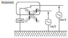
Do not contact a single Switch to two power supplies that are different in polarity or type.
Connection of Different Polarities
The power supply may short-circuit if the loads are connected in the way shown in the “incorrect” example below.
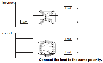
Even in the “correct” example, note that the insulation performance of the switch may deteriorate and the switch life may be shortened because loads are connected to both contacts.
Connection of Different Power Supplies
The DC and AC power may be mixed for the circuit shown below.
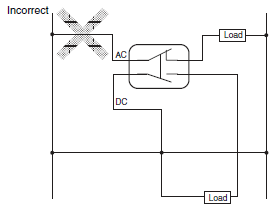
Do not design a circuit where voltage is imposed between contacts, otherwise contact weld may result.
3. Contact Protective Circuit
Apply a contact protective circuit to extend the contact life, prevent noise, and suppress the generation of carbide or nitric acid. Be sure to apply the contact protective circuit correctly, otherwise an adverse effect may occur. The following provides typical examples of contact protective circuits. If the Limit Switch is used in an excessively humid location for switching a load that easily generates arcs, such as an inductive load, the arcs may generate NOx, which will change into HNO3 if it reacts with moisture. Consequently, the internal metal parts may corrode and the Limit Switch may fail. Be sure to select the ideal contact preventive circuit from the following.
Typical Examples of Contact Protective Circuits
| Circuit example | Applicable current | Feature and details | Element selection | ||
| AC | DC | ||||
| CR circuit |  | * | Yes | * When AC is switched, the load impedance must be lower than the CR impedance. | C: 1 to 0.5 μF × switching current (A) R: 0.5 to 1 Ω × switching voltage (V) The values may change according to the characteristics of the load. The capacitor suppresses the spark discharge of current when the contacts are open. The resistor limits the inrush current when the contacts are closed again. Consider the roles of the capacitor and resistor and determine ideal capacitance and resistance values through testing. Basically, use a capacitor with a dielectric strength between 200 and 300 V. When AC is switched, make sure that the capacitor has no polarity. |
 | Yes | Yes | The operating time will be greater if the load is a relay or solenoid. Connecting the CR circuit in parallel to the load is effective when the power supply voltage is 24 or 48 V and in parallel to the contacts when the power supply voltage is 100 to 200 V. | ||
| Diode method |  | No | Yes | Energy stored in the coil is changed into current by the diode connected in parallel to the load. Then the current flowing to the coil is consumed and Joule heat is generated by the resistance of the inductive load. The reset time delay with this method is longer than that in the CR method. | The diode must withstand a peak inverse voltage 10 times higher than the circuit voltage and a forward current as high or higher than the load current. |
| Diode and Zener diode method |  | No | Yes | This method will be effective if the reset time delay caused by the diode method is too long. | Use a Zener diode with a Zener voltage that is approximately 1.2 × power supply voltage as, depending on the environment, the load may not operate. |
| Varistor method |  | Yes | Yes | This method makes use of constant-voltage characteristic of the varistor so that no high-voltage is imposed on the contacts. This method causes a reset time delay. Connecting a varistor in parallel to the load is effective when the supply voltage is 24 to 48 V and in parallel to the contacts when the supply voltage is 100 to 200 V. | --- |
Do not apply contact protective circuits as shown below.
 | This circuit effectively suppresses arcs when the contacts are OFF. The capacitor will be charged, however, when the contacts are OFF. Consequently, when the contacts are ON again, short-circuited current from the capacitance may cause contact weld. |
 | This circuit effectively suppresses arcs when the contacts are OFF. When the contacts are ON again, however, charge current will flow to the capacitor, which may result in contact weld. |
Switching a DC inductive load is usually more difficult than switching a resistive load.
By using an appropriate contact protective circuit, however, switching a DC inductive load will be as easy as switching a resistive load.
4. Switching
Do not use the Switch for loads that exceed the rated switching capacity or other contact ratings. Doing so may result in contact weld, contact separation failures, or insulation failures. Furthermore, the Switch may be broken or damaged.
Do not touch the charged switch terminals while power is supplied, otherwise an electric shock may be received.
The life of the Switch varies greatly with switching conditions. Before using the Switch, be sure to test the Switch under actual conditions. Make sure that the number of switching operations is within the permissible range. If a deteriorated Switch is used continuously, insulation failures, contact weld, contact failures, switch damage, or switch burnout may result.
Do not apply excessive or incorrect voltages to the Switch or incorrectly wire the terminals. Otherwise, the Switch may not function properly and have an adverse effect on external circuitry. Furthermore, the Switch itself may become damaged or burnt.
Do not use the Switch in locations where flammable or explosive gases are present. Otherwise switching arcs or heat radiation may cause a fire or explosion.
Do not drop or disassemble the Switch, otherwise it may not be capable of full performance. Furthermore, it may be broken or burnt.
Mechanical Conditions
Operating Force and Operating Method
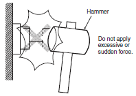
Fingertip operation is an important feature of Pushbutton Switches. In terms of Switch operation, Pushbutton Switches differ greatly from detection switches such as Basic Switches. Operating the Switch using a hard object (e.g., metal), or with a large or sudden force, may deform or damage the Switch, resulting in faulty or rough operation, or shortening of the Switch life. The strength varies with the size and construction of the Switch. Use the appropriate Switch for the application after confirming the operating method and operating force with this catalog.
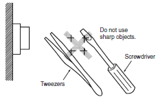
The pushbutton surface is composed of resin. Therefore, do not attempt to operate the pushbutton using a sharp object, such as a screwdriver or a pair of tweezers. Doing so may damage or deform the pushbutton surface and result in faulty operation.
Mounting
Switches can be broadly divided into two categories according to mounting method: panel-mounting models and PCB-mounting models. Use the appropriate model for the mounting method required. Basically, panel-mounting Switches can withstand a greater operating force than PCB-mounting Switches. If, however, the panel thickness or the panel-cutout dimensions are not suitable for the Switch, it may not be able to withstand the normal operating force. With continuous mounting in particular, select a panel of a thickness that is easily sufficient to withstand the total operating force.
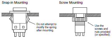
Panel-mounting Switches can be divided into two categories according to the mounting method: snap-in mounting models and screw-mounting models. Snap-in mounting Switches are held in place with the elasticity of resin or a metal leaf spring. Do not attempt to modify the spring after mounting. Doing so may result in faulty operation or damage the mounting structure. Mount screwmounting models using the screws and nuts provided (or individually specified). Tighten the screws to the specified torque. Mounting with different screws or nuts, or tightening beyond the specified torque may result in distortion of the inside of the case or damage to the screw section.
Subjecting the Switch to severe vibrations or shock may result in faulty operation or damage. Also, many of the Switches are composed of resin so contact with sharp objects may result in damage to the surface. This kind of damage may spoil the appearance of the Switch or result in faulty operation. Do not throw or drop the Switch.
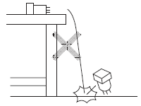
Do not drop or knock the Switch.
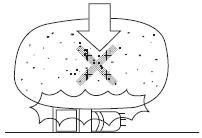
Do not drop objects or place heavy objects on the Switch.
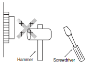
Do not operate the Switch with heavy or sharp objects.
Mounting Precautions
Wiring
Perform wiring so that the lead wires will not be caught on other objects as this will cause stress on the Switch terminals. Wire the Switch so that there is slack in the lead wires and fix lead wires at intermediate points. If the panel to which the Switch is mounted needs to be opened and closed for maintenance purposes, perform wiring so that the opening and closing of the panel will not interfere with the wiring.
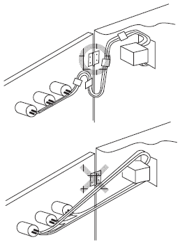
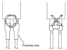
With miniature Switches, the gap between the terminals is very narrow. Use protective or heat-absorbing tubes to prevent burning of the wire sheath or shorting.
Soldering
There are two methods for soldering the Switch: hand soldering and automatic soldering. In addition, automatic soldering itself can be divided into two types: dip soldering and reflow soldering. Use the soldering method appropriate for the mounting method.
Typical Soldering Example
| Method | Soldering device | Application | |
| Hand soldering | Soldering iron | Small quantities Different materials Lead wire terminals | |
| Automatic soldering | Dip soldering | Jet soldering bath Dip soldering bath | Large quantities of discrete terminals |
| Reflow soldering | Infrared reflow (IR) soldering bath Vapor-phase (VPS) reflow soldering bath | Large quantities of miniature SMD terminals | |
Do not use soldering flux that contains chlorine. Doing so may result in metal corrosion.
Perform hand soldering using the appropriate soldering iron.
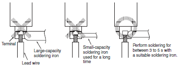
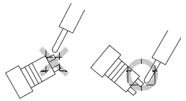
With the exception of PCB-mounting Switches, when performing hand soldering, hold the Switch so that the terminals point downwards so that flux does not get inside the Switch.
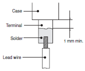
Leave a gap of at least 1 mm between the soldered parts and the surface of the case so that flux does not get inside the Switch.
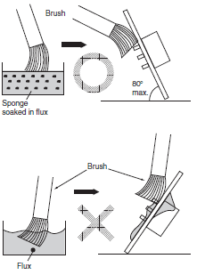
When applying flux using a brush, use a sponge soaked in flux as shown below. Do not apply more than is necessary. Also, apply the flux with the PCB inclined at an angle of less than 80° so that flux does not flow onto the mounting surface of the Switch.
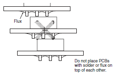
Do not place PCBs that have had flux applied or have been soldered on top of each other. Otherwise, the flux on the PCBs solder surface may stain the upper part of the Switch or even permeate the inside of the Switch and cause contact failure. Be sure to insert a special PCB stocker.
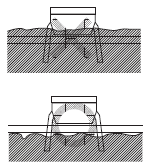
When performing soldering with a dip soldering bath, ensure that the flux does not reach a higher level than the PCB.
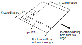
Flux is especially likely to rise up at the edges of the PCB. If the Switch is mounted near the edge of the PCB, create a gap between the edge by using a split PCB, and insert the PCB in the soldering bath so that the edge that is farthest from the Switch enters the bath first.
Storage
When the Switch is left unused or stored for long periods, the ambient conditions can have a great effect on the condition of the Switch. In certain environments, leaving the Switch exposed may result in deterioration (i.e., oxidation, or the creation of an oxide film) of the contacts and terminals, causing the contact resistance to increase, and making it difficult to solder the lead wires. Therefore, store in a well-ventilated room, inside, for example, a non-hygroscopic case, in a location where no corrosive gases are present.
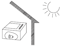
If the Switch is stored in a location where it will be exposed to direct light, colored resin in the colored plate may fade. Therefore, do not store the Switch in locations where it will be exposed to direct light.


