 Cautions
-
 Safety Components
-
 Safety Sensors
-
 Safety Door Switches
- Safety Limit Switches
-
 Safety Relays
-
Safety Limit Switches
|
|
| Precautions for Correct Use |
| Safety Precautions |
Precautions for Correct Use
Mechanical Characteristics
Operating Force, Stroke, and Contact Characteristics
The following graph indicates the relationship between operating force and stroke or stroke and contact force. In order to operate the Limit Switch with high reliability, it is necessary to use the Limit Switch within an appropriate contact force range. If the Limit Switch is used in the normally closed condition, the dog must be installed so that the actuator will return to the FP when the actuator is actuated by the object. If the Limit Switch is used in the normally open condition, the actuator must be pressed to 80% to 100% of the OT (i.e., 60% to 80% of the TT) and any slight fluctuation must be absorbed by the actuator.
If the full stroke is set close to the OP or RP, contact instability may result. If the full stroke is set to the TTP, the actuator or switch may become damaged due to the inertia of the dog. In that case, adjust the stroke with the mounting panel or the dog. Refer to Dog Design, Stroke Settings vs. Dog Movement Distance, and Dog Surface for details.
The following graph shows an example of changes in contact force according to the stroke. The contact force near the OP or RP is unstable, and the Limit Switch cannot maintain high reliability. Furthermore, the Limit Switch cannot withstand strong vibration or shock.
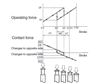
If the Limit Switch is used so that the actuator is constantly pressed, it will fail quickly and reset faults may occur. Also, perform maintenance and inspections periodically ,when moving the cam or dog while they are in contact with the Switch actuator (roller), as the movement distance increases the wear on the roller and the roller axis will increase.
Operation
Carefully determine the proper cam or dog so that the actuator will not abruptly snap back, thus causing shock. In order to operate the Limit Switch at a comparatively high speed, use a cam or dog with a long enough stroke that keeps the Limit Switch turned ON for a sufficient time so that the relay or valve will be sufficiently energized.
The operating method, the shape of the dog or cam, the operating frequency, and the travel after operation have a large influence on the durability and operating accuracy of the Limit Switch. The cam must be smooth in shape.
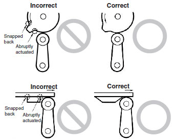
Appropriate force must be imposed on the actuator by the cam or another object in both rotary operation and linear operation. If the object touches the lever as shown below, the operating position will not be stable.
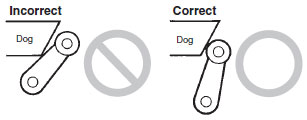
Unbalanced force must not be imposed on the actuator. Otherwise, wear and tear on the actuator may result.
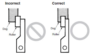
Make sure that the actuator does not exceed the OT (overtravel) range, otherwise the Limit Switch may malfunction. When mounting the Limit Switch, be sure to adjust the Limit Switch carefully while considering the whole movement of the actuator.
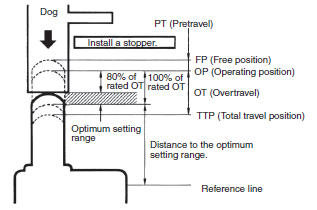
The Limit Switch may soon malfunction if the OT is excessive. Therefore, adjustments and careful consideration of the position of the Limit Switch and the expected OT of the actuator are necessary when mounting the Limit Switch.
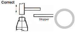
Be sure to use the Limit Switch according to the characteristics of the actuator.
If a roller arm lever actuator is used, do not attempt to actuate the Limit Switch in the direction shown below.

Do not modify the actuator to change the OP.
In the case of a long actuator of an adjustable roller lever type, the following countermeasures against lever shaking are recommended.
1.Make the rear edge of the object smooth with an angle of 15° to 30° or make it in the shape of a quadratic curve.
2.Design the circuit so that no error signal will be generated.
3.Use or set a switch that is actuated in one direction only.
(Also, set the switch for operation in one direction only.)
Operating Environment
These Switches are for indoor applications. The Switches may fail if they are used outdoors.
Do not use the Switch in locations where toxic gases, such as H2S, SO2, NH3, HNO3, and Cl2, may be present, or in locations that are subject to high temperatures or humidity. Doing so may damage the Switch due to contact failure or corrosion.
Do not use the Switches in the following locations.
*Locations subject to severe temperature changes
*Locations subject to high temperatures or condensation
*Locations subject to severe vibration
*Locations where the interior of the Protective Door may come into direct contact with cutting chips, metal filings, oil, or chemicals
*Locations where the Switch may come into contact with thinner or detergents
*Locations where explosive or flammable gases are present
Switch Contacts
Switch contacts can be used with both standard loads and microloads, but once a contact has been used to switch a standard load, it cannot be used for a load of a smaller capacity. Doing so may result in roughening of the contact surface and contact reliability may be lost.
Storing Switches
Do not store the Switch in locations where toxic gases, such as H2S, SO2, NH3, HNO3, and Cl2, may be present, or in locations that are subject to, excessive dirt, excessive dust, high temperature, or high humidity.
Other Precautions
When attaching a cover, be sure that the seal rubber is in place and that there is no foreign material present. If the cover is attached with the seal rubber out of place or if foreign material is stuck to the rubber, a proper seal will not be obtained.
Perform maintenance inspections periodically.
Use the Switch with a load current that does not exceed the rated current.
Do not use any screws to connect the cover other than the specified ones. The seal characteristics may be reduced.
Dog Design
Operating Speed, Dog Angle, and Relationship with Actuator
Before designing a dog, carefully consider the operating speed and angle of the dog and their relationship with the shape of the actuator. The optimum operating speed (V) of a standard dog at an angle of 30° to 45° is 0.5 m/s maximum.
Roller Lever Models
1.Non-overtravel Dog
Dog speed: 0.5 m/s max. (Standard Speed)

| Φ | V max. (m/s) | y |
| 30° | 0.4 | 0.8 (TT) 80% of total travel |
| 45° | 0.25 | |
| 60° | 0.1 | |
| 60° to 90° | 0.05 (low speed) |
Dog speed: 0.5 m/s ≤ V ≤ 2 m/s (High Speed)

| θ | Φ | V max. (m/s) | y |
| 45° | 45° | 0.5 | 0.5 to 0.8 (TT) |
| 50° | 40° | 0.6 | |
| 60° to 55° | 30° to 35° | 1.3 | 0.5 to 0.7 (TT) |
| 75° to 65° | 15° to 25° | 2 |
Note:The above y values indicate the ratio ranges based on TT (total travel).
Therefore, the optimum pressing distance of the dog is between 50% and 80% (or 50% and 70%).
2.Overtravel Dog
Dog speed: 0.5 m/s max.

| Φ | V max. (m/s) | y |
| 30° | 0.4 | 0.8 (TT) 80% of total travel |
| 45° | 0.25 | |
| 60° | 0.1 | |
| 60° to 90° | 0.05 (low speed) |
Dog speed: 0.5 m/s min.
If the speed of the overtravel dog is comparatively high, make the rear edge of the object smooth at an angle of 15° to 30° or make it in the shape of a quadratic curve. Then lever shaking will be reduced.

| θ | Φ | V max. (m/s) | y |
| 45° | 45° | 0.5 | 0.5 to 0.8 (TT) |
| 50° | 40° | 0.6 | |
| 60° to 55° | 30° to 35° | 1.3 | 0.5 to 0.7 (TT) |
| 75° to 65° | 15° to 25° | 2 |
Note:The above y values indicate the ratio ranges based on TT (total travel). Therefore, the optimum pressing distance of the dog is between 50% and 80% (or 50% and 70%).
Plunger Models
If the dog overrides the actuator, the front and rear of the dog may be the same in shape, provided that the dog is not designed to be separated from the actuator abruptly.
Roller Plunger

| Φ | V max. (m/s) | y |
| 30° | 0.25 | 0.6 to 0.8 (TT) |
| 20° | 0.5 | 0.5 to 0.7 (TT) |
Stroke Settings vs. Dog Movement Distance
The following provides information on stroke settings based on the movement distance of the dog instead of the actuator angle. The following is the optimum stroke of the Limit Switch.
Optimum stroke: PT + {Rated OT × (0.7 to 1.0)}
The angle converted from the above: θ1 + θ2
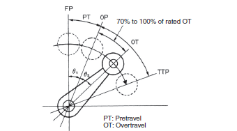
The movement distance of the dog based on the optimum stroke is expressed by the following formula.
Movement distance of dog
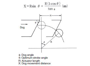
The distance between the reference line and the bottom of the dog based on the optimum stroke is expressed by the following formula.
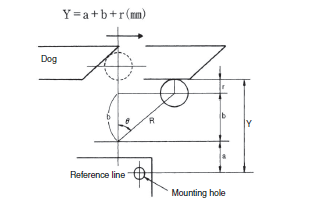
a:Distance between reference line and actuator fulcrum
b:R cosθ
r:Roller radius
Y:Distance between reference line and bottom of dog
Dog Surface
The surface of dog touching the actuator should be 6.3 S in quality and hardened at approximately HV450.
For smooth operation of the actuator, apply molybdenum disulfide grease to the actuator and the dog touching the actuator.
Others
When using the Limit Switch with a long lever or long rod lever, make sure that the lever is in the downward direction.
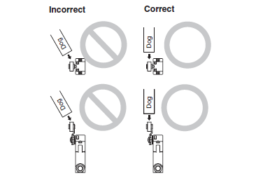
With a roller actuator, the dog must touch the actuator at a right angle. The actuator or roller may deform or break if the dog touches the actuator (roller) at an oblique angle.
Do not remove the Head. The Switch may fail.


