Safety Sensors
|
|
| Precautions for Correct Use |
| Safety Precautions |
Precautions for All Safety Sensors

Installation Conditions
Detection Zone and Intrusion Path
Install a protective structure so that the hazardous part of a machine can only be reached by passing through the ensor's detection zone. Install the ensors so that part of the person is lways present in the detection zone when orking in a machine's hazardous areas.
If a person is able to step into the azardous area of a achine and remain behind the Safety Light Curtain's etection zone, configure the system with an interlock unction that prevents the machine from being restarted.
Otherwise it may result in heavy injury.

Correct Installation
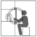
A person can only reach the hazardous part of the machinery by passing through the sensor's detection zone.
Correct Installation
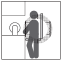
A person enters the detection zone during operation.
Incorrect Installation
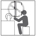
A person can reach the hazardous part of the machinery without passing through the sensor's detection zone.
Incorrect Installation
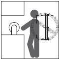
A person is between the sensor's detection zone and the hazardous part of the machinery.
Install the interlock reset switch in a location that provides a clear view of the entire hazardous area and where it cannot be activated from within the hazardous area.

The Safety Light Curtain cannot protect a person from an object flying from a hazardous area. Install protective cover(s) or fence(s).

Safety Distance
The safety distance is the distance that must be set between the Safety Sensor and a machine's hazardous part to stop the hazardous part before a person or object reaches it. The safety distance varies according to the standards of each country and the individual specifications of each machine. In addition, the calculation of the safety distance differs if the direction of approach is not perpendicular to the detection zone of the Safety Sensor.
Always refer to relevant standards.
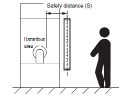
Make sure to secure the safety distance (S) between the Safety Sensor and the hazardous part. Otherwise, the machine may not stop before a person reaches the hazardous part, resulting in serious injury.

Note:The response time of a machine is the time period from when the machine receives a stop signal to when the machine's hazardous part stops.
Measure the response time on the actual system. Also, periodically check that the response time of the machine has not changed.
<Safety Distance for a Safety Light Curtain>
How to calculate the safety distance specified by International standard ISO13855-2002 (European standard EN999-1999)
(Reference)
If a person approaches the detection zone of the Safety Light Curtain perpendicularly, calculate the safety distance as shown below.
S = K x T + C . . . Eq. (1)
S: Safety distance
K: Approach speed to the detection zone
T: Total response time of the machine and Safety Light Curtain
C: Additional distance calculated by the detection capability of the Safety Light Curtain
<System that has detection capability of 40 mm max.>
Use K = 2,000 mm/s and C = 8 x (d - 14 mm) in equation (1) for the calculation.
S = 2,000 mm/s x (Tm + Ts) + 8 x (d - 14 mm)
S = Safety distance (mm)
Tm = Machine's response time (s)
Ts = Response time of the Safety Light Curtain from ON to OFF (s) *
d = Size of Safety Light Curtain‘s detection capability (mm) *
*These values differ depending on the Switch. Refer to the “Precautions for Correct Use” for the Switch you are using.
[Calculation example]
When Tm = 0.05 s, Ts = 0.01 s, and d = 14 mm:
S = 2,000 mm/s x (0.05 s + 0.01 s) + 8 x (14 mm - 14 mm) = 120 mm . . . Eq. (2)
If the result is less than 100 mm, use S = 100 mm.
If the result exceeds 500 mm, use the following equation where K = 1,600 mm/s.
S = 1,600 mm/s x (Tm + Ts) + 8 x (d - 14 mm) . . . Eq. (3)
If the result of this Eq. (3) is less than 500 mm,
use S = 500 mm.
<Systems with a Smallest Detectable Object Size (Diameter) Greater than 40 mm or Systems Using Multi-beam Safety Sensors>
Assuming K = 1,600 mm/s and C = 850 mm, the following calculation is made using Eq. (1).
S = 1,600 mm/s x (Tm + Ts) + 850 ... Eq. 4,
S = Safety distance (mm)
Tm = Machine's response time (s)
Ts = Response time of the Safety Light Curtain from ON to OFF (s)
Calculation example:
When Tm = 0.05 s and Ts = 0.01 s,
S = 1,600 mm/s x (0.05 s + 0.01 s) + 850 mm = 946 mm
How to calculate the safety distance specified by American standard ANSI B11.19
(Reference)
<Systems with a Smallest Detectable Object Size (Diameter) Less than 64 mm>
If a person approaches the detection zone of the Safety Light Curtain perpendicularly, calculate the safety distance as shown below.
S = K x (Ts + Tc + Tr + Tbm) + Dpf
S: Safety distance
K: Approach speed to the detection zone (the value recommended by OSHA standard is 1,600 mm/s)
Approach speed K is not specified in the ANSI B.11.19 standard. To determine the value of K to apply, consider all factors, including the operator's physical ability.
Ts = Machine's stop time (s)
Tr = Response time of the Safety Light Curtain from ON to OFF (s)
Tc = Machine control circuit's maximum response time required to activate its brake (s)
Tbm = Additional time (s)
If a machine has a brake monitor, "Tbm = Brake monitor setting time - (Ts + Tc)". If it has no brake monitor, we recommend using 20% or more of (Ts + Tc) as additional time.
Dpf = Additional distance
According to ANSI's formula, Dpf is calculated as shown below:
Dpf = 3.4 x (d - 7.0): Where d is the detection capability of the Safety Light Curtain (unit: mm)
[Calculation example]
When K = 1,600 mm/s, Ts + Tc = 0.06 s, brake monitor setting time = 0.1 s, Tr = 0.01 s, d = 14 mm:
Tbm = 0.1 - 0.06 = 0.04 s
Dpf = 3.4 x (14 - 7.0) = 23.8 mm
S = 1,600 x (0.06 + 0.01 + 0.04) + 23.8 = 199.8 mm
Method for Calculating the Safety Distance as Provided by ANSI/RIA R15.06 (USA)
(Reference)
<Systems with a Smallest Detectable Object Size (Diameter) Greater than 64 mm and Less than 600mm>
The safety distance is calculated based on the following concepts when the human body intrudes perpendicular to the detection zone of the Safety Light Curtain.
S = K x (Ts + Tc + Tr ) + Dpf
S: Safety distance
K = Intrusion speed into detection zone (1,600 mm/s min. recommended by OSHA)
Ts = Stop time of machine/equipment (s)
Tr = Light curtain ON-to-OFF response time (s)
Tc = Maximum response time of the machine/equipment braking circuit required to operate the brake (s)
Dpf = Additional distance (mm)
If the Sensor is installed with the lowest beam height above the floor at 300 mm or lower and the highest beam height above the floor at 1,200 mm or higher, the Dpf will be 900 mm.
If the Sensor is installed with the lowest beam height above the floor at 300 mm or lower and the highest beam height above the floor at 900 mm or higher, the Dpf will be 1,200 mm.
[Calculation example]
K = 1,600 mm/s, Ts + Tc = 0.06s,
If Tr = 0.01 s and Dpf = 900 mm:
S = 1,600 x (0.06 + 0.01) + 900 = 1,012 mm
Height of the lowest beam
= 300 mm or less Height of the highest beam
= 1,200 mm or greater
Dpf=900mm
Height of the lowest beam
= 300 mm or less
Height of the highest beam
= 900 mm or greater
Dpf=1,200mm
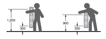
<Safety Distance for a Single-beam Safety Sensor>
How to calculate the safety distance specified by International standard ISO13855-2002 (European standard EN999-1999)
(Reference)
(With Intrusion Perpendicular to the Detection Zone)
Safety distance (S) = Intrusion speed into the detection zone (K) x Total response time for the machine and Sensor (T) + Additional distance calculated based on the detection capability of the Sensor (C)
The safety distance varies with national standards and individual machine standards. The equation is also different if the direction of intrusion is not perpendicular to the detection zone of the Sensor. Be sure to refer to related standards.
Here T = T1 + T2 + T3
Where
T1 = Maximum machine stop time (s)
T2 = Sensor response time (s)
(From ON to OFF: 2.0 ms for the E3FS, 1.0 ms for the E3ZS, 35 ms for the F3SS)
T3 = F3SX response time (s)
(From ON to OFF: Refer to Response Time.)
The maximum stop time for a machine is the time it takes to actually stop dangerous parts after the machine receives a stop signal from the F3SX.

Measure the actual maximum stop time for the machine and the periodically check it to see if the time changes.

K and C are as follows for Single-beam Safety Sensors.
1.When a Single-beam Safety Sensor is used alone (when the risk assessment indicates that a single beam is sufficient)
K = 1,600 mm/s
C = 1,200 mm
Height of the beam from the ground or from a reference surface: 750 mm (EN999 recommendation)
2.When multiple Single-beam Safety Sensors are installed at different heights.
K = 1,600 mm/s
C = 850 mm
The beam heights in the following table are the EN999 recommendations.
| No. of beams | Height from the reference surface (example: the floor) |
| 2 | 400 mm, 900 mm |
| 3 | 300 mm, 700 mm, 1100 mm |
| 4 | 300 mm, 600 mm, 900 mm, 1200 mm |
Distance from Glossy Surface
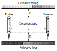
Install the sensor system so that it is not affected by reflection from a glossy surface. Failure to do so may hinder detection, resulting in serious injury.

Install the sensor system at distance D or further from highly reflective surfaces such as metallic walls, floors, ceilings, or workpieces, as shown below.

<Side View>
<Top View>
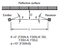
| Distance betweenemitter and receiver(Detection Distance) | Allowable installation distance D | |
| Type 4 | Type 2 | |
| For 0.2 to 3 m | 0.13 m | 0.26 m |
| For 3 m or more | L/2 x tan5° = L x 0.044 (m) | L/2 x tan10° = L x 0.088 (m) |
Others
To use the Safety Light Curtain in PSDI mode (restart of cycle operation by the sensor), you must configure an appropriate circuit between the Safety Light Curtain and the machine. For details about PSDI, refer to OSHA1910.217, IEC61496-1, and other relevant standards and regulations.

Do not try to disassemble, repair, or modify this product.
Doing so may cause the safety functions to stop working properly.

Do not use the Safety Light Curtain in environments where flammable or explosive gases are present. Doing
so may result in explosion.

Perform daily and 6-month inspections for the Safety Light Curtain. Otherwise, the system may fail to work properly, resulting in serious injury.

Installation
Prevention of Mutual Interference
The emitter and the receiver to be set facing each other should be a pair of the same set. Erroneous combination may create a zone where objects cannot be detected.

Do not use a sensor system in a reflective configuration.
Doing so may hinder detection.
Mirrors can be used change the optical route.

When using more than 1 set of Safety Light Curtain, install them so that mutual interference does not occur, such as by configuring series connections or using physical barriers between adjacent sets.


